
- お役立ち記事
- Tolerance Design and Geometric Dimensioning and Tolerancing (GD&T) Techniques
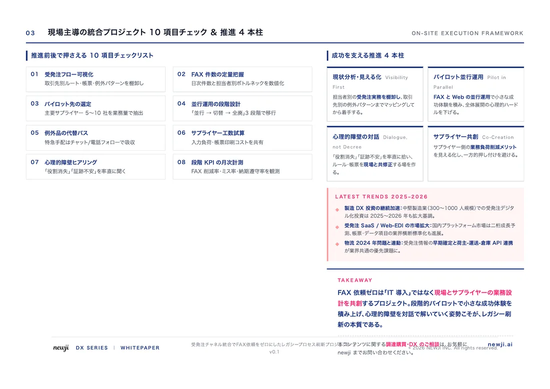
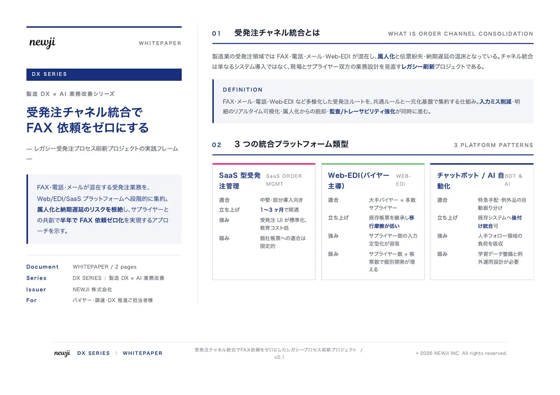
スタートアップから大手まで。
調達・受発注をAIで標準化。
相見積比較も進捗管理もAIが下支え。取引先は招待で完全無料。

Tolerance Design and Geometric Dimensioning and Tolerancing (GD&T) Techniques

目次
Understanding Tolerance Design
Tolerance design is a crucial aspect of manufacturing and engineering.
Essentially, it refers to how much deviation from the intended dimensions of a part is acceptable.
Every manufactured part will naturally have some variation, but these variations need to be within specific limits, known as tolerances, for the part to function correctly.
Why Tolerance Design Matters
Tolerance design is significant for several reasons.
First, it ensures that parts will fit together properly in an assembly.
If tolerances are too loose, parts may be too big or too small, leading to poor fit or performance issues.
On the other hand, if tolerances are too tight, manufacturing costs can increase due to the need for more precise and expensive production processes.
Moreover, proper tolerance design can improve product quality and reliability.
When tolerances are well-defined and consistently met, it reduces the risk of parts failing prematurely or causing system malfunctions.
Geometric Dimensioning and Tolerancing (GD&T) Basics
Geometric Dimensioning and Tolerancing (GD&T) is a system that complements tolerance design.
It provides a standardized way to specify and communicate tolerances in technical drawings.
Key GD&T Symbols
Understanding the key GD&T symbols is fundamental to applying this technique effectively.
The most common symbols include:
1. **Feature Control Frame**: This is a rectangular box containing geometric characteristics, tolerances, and datum references.
2. **Datum**: A datum is a theoretical point, line, plane, or cylinder from which measurements are taken.
3. **Straightness**: Indicates that the element must lie within two parallel lines or planes.
4. **Flatness**: Ensures that a surface is within two parallel planes.
5. **Circularity**: Ensures that all points on a surface must lie within a concentric circle.
6. **Cylindricity**: Ensures that all points along the cylindrical surface are within two concentric cylinders.
7. **Profile**: Controls the form of a surface by defining a boundary.
8. **Parallelism**: Ensures that a surface or axis is parallel to a datum.
9. **Perpendicularity**: Ensures that a surface or axis is perpendicular to a datum.
10. **Angularity**: Controls the relationship of one surface or axis to another at a specific angle.
Advantages of Using GD&T
Implementing GD&T has several advantages.
Firstly, it provides a clear and concise way to communicate how a part should be manufactured.
This reduces misunderstandings and misinterpretations between designers and manufacturers.
Secondly, GD&T allows for more flexibility in manufacturing.
Instead of specifying exact dimensions, it defines acceptable limits, which can be more cost-effective.
Lastly, GD&T improves the functionality and reliability of products.
By controlling specific geometric features, you can ensure consistency and improve the performance of assembled products.
Applying Tolerance Design and GD&T Techniques
Integrating tolerance design and GD&T into your engineering and manufacturing processes can seem daunting.
However, following some basic steps can make the process more manageable.
Step 1: Define Critical Features
Start by identifying the critical features of the part that need tight tolerances.
These features are often related to fit, function, or performance.
For instance, holes that need to align for assembly are typically considered critical.
Step 2: Choose Appropriate Tolerances
Next, assign tolerances based on the functionality of each feature.
Consider the consequences if the part is at the high or low end of the tolerance range.
For critical features, tighter tolerances may be necessary, while non-critical features can have looser tolerances.
Step 3: Apply GD&T Symbols
Use GD&T symbols to specify the tolerances in your technical drawings.
Include feature control frames and datums to provide guidance about how the part should be measured and inspected.
Ensure that all team members understand the GD&T symbols and their implications.
Step 4: Verify and Inspect
Finally, once the part is manufactured, it’s essential to verify that the tolerances have been met.
Use precision measuring tools like calipers, micrometers, and coordinate measuring machines (CMMs) to check the dimensions and geometric features.
Challenges and Solutions in Tolerance Design and GD&T
Despite their benefits, tolerance design and GD&T also come with challenges.
For instance, over-complicating designs with unnecessary tight tolerances can drive up costs without any real benefit.
Communication gaps between design and manufacturing teams can also lead to inconsistencies and errors.
Addressing Common Issues
To overcome these challenges, consistent communication and collaboration are essential.
Ensure regular meetings between designers and manufacturers to discuss the tolerances and their impact on production.
Training is another crucial aspect.
Make sure all team members are well-versed in GD&T symbols and their applications.
Investing in training can minimize errors and improve overall efficiency.
Moreover, use simulation software to analyze tolerance stack-ups and their impact on the final assembly.
This proactive approach can save time and money by identifying potential issues early in the design phase.
The Future of Tolerance Design and GD&T
As technology evolves, so do the tools and techniques used in tolerance design and GD&T.
Advancements in 3D modeling and computer-aided design (CAD) software are making it easier to apply these principles accurately.
Emerging technologies like digital twins and augmented reality (AR) are also set to revolutionize how we approach tolerance design and GD&T.
These technologies can provide real-time feedback and alert engineers to potential issues before they become critical.
Moreover, as manufacturing moves toward more automated and smart factories, the need for precise and reliable tolerance design and GD&T will only grow.
These systems will be essential for ensuring that automated machines produce components consistently within the required tolerances.
In conclusion, understanding and implementing tolerance design and GD&T techniques can significantly improve your manufacturing processes.
By carefully defining tolerances and using standardized symbols, you can ensure that parts fit together properly, function well, and are cost-effective to produce.
While challenges exist, consistent communication, ongoing training, and the use of advanced tools can help you navigate these complexities and achieve high-quality results.
この記事の理解を深める
無料ホワイトペーパーをプレゼント
製造業の現場で使える実務資料(PDF)を無料でお届けします。"こんな資料が届きます" ↓ 下のボタンからどうぞ。
PRODUCT — 製造業向け 調達・受発注クラウド
この記事の課題、
newji で解決しませんか?
newji は、製造業の調達・受発注に特化したクラウド/AIエージェント。見積依頼・発注書作成・進捗管理・承認をひとつの画面に集約し、AIが比較と異常検知を担当。最後の「GO」だけ人が押す仕組みです。
- 見積〜発注〜納期を一元管理。催促・転記のムダをゼロに
- AIが相見積もり比較と異常検知。あなたは判断だけに集中
- 取引先は「招待」で完全無料。自社コストだけで取引先ごとデジタル化
※ 取引先から招待された企業様は完全無料でご利用いただけます


