

- お役立ち記事
- Techniques for improving mechanical drawing quality using geometric tolerances

Techniques for improving mechanical drawing quality using geometric tolerances

目次
Understanding Geometric Tolerances
Geometric tolerances are a vital aspect of mechanical drawing and engineering.
They define the allowable variation in the geometry of a part, ensuring that parts fit together properly and function as intended.
By understanding these tolerances, designers and engineers can create more precise and reliable mechanical drawings.
Geometric tolerances specify the permissible limits of form, orientation, location, and runout of a feature.
They provide a way to communicate the acceptable level of variation in each part of a component.
This level of specificity helps prevent errors in the manufacturing process and ensures the end product meets its intended purpose.
The Importance of Geometric Tolerances
Implementing geometric tolerances in mechanical drawing is crucial for several reasons.
Firstly, it enhances the interchangeability of parts.
When components are designed to fit within specific tolerances, they can be manufactured in different locations, yet still assemble correctly without custom adjustments.
Secondly, geometric tolerances improve the functionality and performance of mechanical systems.
Accurate tolerances ensure that parts fit snugly without unwanted gaps or overlaps, leading to increased efficiency and lifespan of the product.
In addition, they contribute to cost savings by reducing waste and rework.
Manufacturers can produce parts with minimal defects, which translates to fewer resources spent on corrections.
Strategies for Improving Drawing Quality
Improving the quality of mechanical drawings requires a strategic approach to applying geometric tolerances.
Here are some techniques that can enhance the precision and clarity of these drawings.
Using Standardized Symbols
One effective way to improve mechanical drawings is by using standardized symbols for geometric tolerances.
These symbols are universally recognized and help convey specific details about the part’s requirements.
This practice minimizes ambiguity and misinterpretation, ensuring that the manufacturing team has a clear understanding of the design.
Standard symbols also facilitate global collaboration, as engineers and manufacturers worldwide can comprehend the tolerance specifications without language barriers.
This promotes consistency across production lines and aids in maintaining quality standards.
Implementing Tolerance Analysis
Conducting tolerance analysis is another critical step in enhancing drawing quality.
This process involves evaluating the cumulative effect of individual tolerances on a complete assembly.
By simulating different scenarios, engineers can identify potential issues related to tolerance stack-up.
Performing a thorough tolerance analysis helps in making informed decisions about which tolerances are critical and which can be relaxed.
This balance is essential for optimizing both the manufacturability and functionality of the design.
Advanced CAD Software Utilization
Leveraging advanced CAD software can significantly improve the accuracy of mechanical drawings.
Modern software programs have built-in tools for applying geometric tolerances directly to the 3D models.
These tools enhance the precision of the drawings and ensure that all necessary details are included.
Additionally, CAD software enables engineers to visualize how each part interacts with others in an assembly.
This capability is invaluable in identifying potential clashes or misalignments that could arise during the manufacturing process.
Regular Training and Knowledge Updates
Continuous education and training are essential for maintaining high-quality mechanical drawings.
As technology evolves, so do the standards and practices in engineering.
Regular workshops and courses can keep engineers updated on the latest developments in geometric tolerancing.
Training sessions also provide an opportunity to share best practices and learn from industry experts.
This knowledge exchange fosters a culture of precision and quality within engineering teams.
Collaboration and Communication
Effective collaboration and communication are key elements in improving mechanical drawing quality.
Designers, engineers, and manufacturers must work closely to ensure that all geometric tolerances are correctly interpreted and applied.
Documenting Detailed Specifications
Creating detailed documentation for each drawing is crucial in conveying the necessary specifications.
This documentation should include clear instructions on the tolerances and their application.
Well-documented drawings help ensure that each team member has a thorough understanding of the design requirements.
Fostering a Feedback Loop
Establishing a feedback loop between designers and manufacturers can lead to significant improvements in drawing quality.
By actively seeking feedback on the feasibility and ease of manufacturing based on the drawings, engineers can make necessary adjustments.
This continuous feedback helps refine the designs and align them more closely with the practicalities of the manufacturing process.
It also opens the door for innovative solutions that might not have been considered initially.
Conclusion
Improving the quality of mechanical drawings through the effective use of geometric tolerances is pivotal for successful engineering projects.
Adopting standardized symbols, conducting thorough tolerance analysis, and utilizing advanced CAD software are essential steps in this process.
Additionally, promoting ongoing training and fostering collaboration and communication within teams can further enhance drawing quality.
By integrating these techniques, engineers can produce precise, reliable mechanical drawings that lead to higher-quality products and increased satisfaction for manufacturers and consumers alike.
この記事の理解を深める
無料ホワイトペーパーをプレゼント
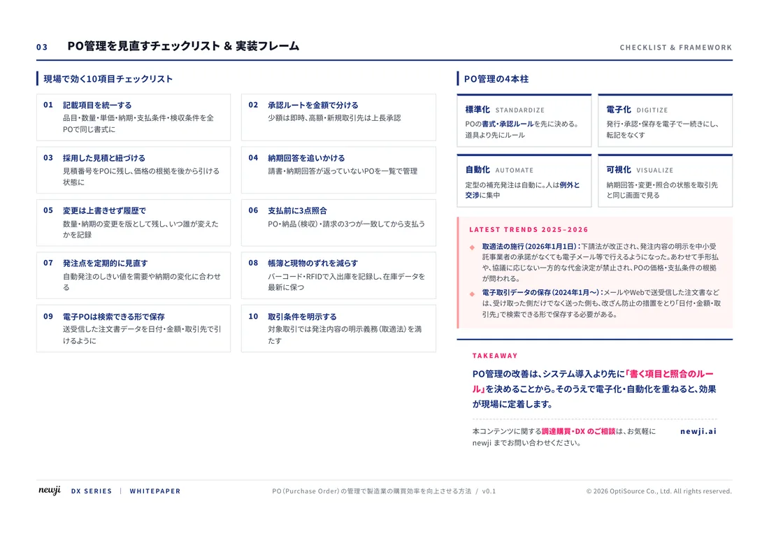
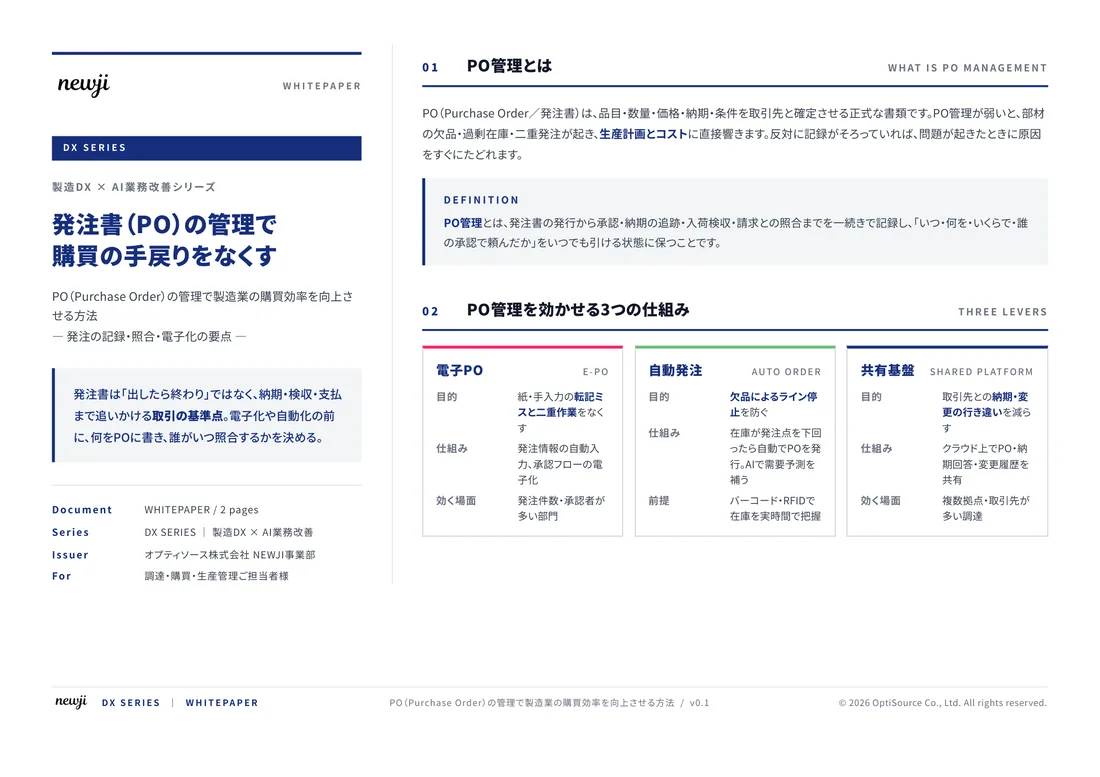
製造業の現場で使える実務資料(PDF)を無料でお届けします。"こんな資料が届きます" ↓ 下のボタンからどうぞ。
FREE DOCUMENT — サービス資料(PDF・無料)
製造業の見積・受発注クラウド
「Newji one」とは
Newji one は、製造業の調達・受発注に特化したクラウド/AIエージェント。見積依頼・発注書作成・進捗管理・承認をひとつの画面に集約し、AIが比較と異常検知を担当。最後の「GO」だけ人が押す仕組みです。
▶ 製造業の見積・受発注クラウド「Newji one」を、資料で見る(PDF・無料)
- 見積〜発注〜納期を一元管理。催促・転記のムダをゼロに
- AIが相見積もり比較と異常検知。あなたは判断だけに集中
- 取引先は「招待」で完全無料。自社コストだけで取引先ごとデジタル化
※ 取引先から招待された企業様は完全無料でご利用いただけます



 NEWJI総研
 OEM/ODM 生産委託
 AI/DX支援
 見積・発注クラウド Newji one
受発注が増えるほど、入力・確認・催促が重くなる。
受発注管理を“仕組み化“して、ミスと工数を削減しませんか。
見積・発注・納期まで一元管理できます。