

- お役立ち記事
- Fundamentals of creating mechanical drawings and points for drawing considering processing and manufacturing

その単価は妥当か。
AI が根拠付きで分析。
相見積の比較も発注も進捗管理も、ひとつの画面に。

Fundamentals of creating mechanical drawings and points for drawing considering processing and manufacturing

目次
Introduction to Mechanical Drawings
Mechanical drawings are crucial in engineering, manufacturing, and construction as they represent the detailed specifications of an object or system.
These drawings provide essential information about the dimensions, materials, and processes needed to produce a particular component or assembly.
Understanding the fundamentals of creating mechanical drawings is vital for engineers, drafters, and technicians to communicate ideas effectively.
Understanding the Basics
Before diving into creating mechanical drawings, it’s important to understand the basic components and types of drawings utilized in the industry.
Mechanical drawings generally include orthographic projections, sectional views, and detailed views.
Orthographic projections offer different views (top, front, side) of an object to provide a comprehensive understanding of its shape and features.
Sectional views display the interior layout of parts, showing the hidden features inside.
Detailed views, on the other hand, focus on specific components that require more precision.
Tools and Equipment
Creating mechanical drawings typically requires a variety of tools and equipment.
Traditional drawing tools include pencils, rulers, compasses, protractors, and drawing boards.
However, with the advent of technology, computer-aided design (CAD) software has become prevalent.
CAD tools offer precise and fast drafting capabilities, allowing for easy revisions and updates.
Some popular CAD software includes AutoCAD, SolidWorks, and CATIA.
Standards and Conventions
Mechanical drawings adhere to established standards and conventions to ensure consistency and clarity.
These standards include line types, dimensions, symbols, and notations, which differ depending on regional guidelines like ISO, ANSI, or DIN.
For instance, lines can represent visible edges, hidden features, or center lines.
Understanding these conventions is essential to interpret and create accurate drawings.
Steps to Create Mechanical Drawings
Creating mechanical drawings involves several steps, each contributing to an accurate and comprehensive document.
Step 1: Define Requirements
The first step in creating a mechanical drawing is to gather all necessary details and requirements.
This phase involves understanding the purpose and function of the component or assembly, as well as its constraints and limitations.
Discussing with stakeholders such as engineers, designers, and fabricators can provide valuable insights.
Step 2: Choose the Right View
Selecting the appropriate views is crucial for a clear understanding of the object.
Depending on the complexity, one may need multiple views like top, front, side, or sectional views.
Choosing the right view aids in avoiding unnecessary confusion.
Step 3: Dimensioning
Dimensioning is one of the most critical aspects of creating a mechanical drawing.
It provides the exact measurements needed to manufacture the product.
Careful consideration must be given to ensure dimensions are clear and in the correct units.
Measurements should be precise and annotated in a way that they cannot be misinterpreted.
Step 4: Incorporate Notes and Symbols
Notes and symbols provide additional information not conveyed through dimensions alone.
They can indicate material specifications, finishes, and assembly instructions.
Standard symbols used for features such as holes, threads, and surface treatments are crucial for maintaining clarity across different teams and locations.
Step 5: Review and Finalize
Before finalizing the drawing, a thorough review is essential.
Check for any errors, omissions, or ambiguities that could affect production.
Collaborating with other experts for a secondary review can catch potential mistakes.
Ensuring that all specifications are met and conforming to standards completes the process.
Considering Manufacturing and Processing
When creating mechanical drawings, it’s vital to consider the manufacturing and processing methods that will follow.
Here are some key points to keep in mind:
Machinability
Understanding the machinability of materials used in your drawings helps in selecting appropriate manufacturing methods.
Choose dimensions and tolerances that match common machining capabilities to avoid costly custom setups.
Tolerances
Tolerances dictate the allowable deviation from specified dimensions.
They play a vital role in the fit and function of the final product.
Designers must set realistic tolerances based on the manufacturing processes to ensure components fit together as intended.
Material Selection
Material selection impacts the production method, cost, and performance of the component.
Be sure to choose materials compatible with the intended manufacturing process and end-use requirements.
Communicate clearly using industry-standard material notations in the drawings.
Assembly Considerations
The design should account for assembly requirements, ensuring easy and efficient assembly of components.
Clear and concise instructions with appropriate symbols will facilitate assembly, reducing errors and time spent.
Conclusion
Creating mechanical drawings is a crucial part of the engineering process that demands attention to detail and a solid understanding of standards and conventions.
By carefully considering the points discussed, you can produce clear and effective drawings that meet both design intentions and manufacturing capabilities.
With practice and adherence to best practices, mechanical drawing can become a strong communication tool, bridging ideas from concept to reality.
この記事の理解を深める
無料ホワイトペーパーをプレゼント
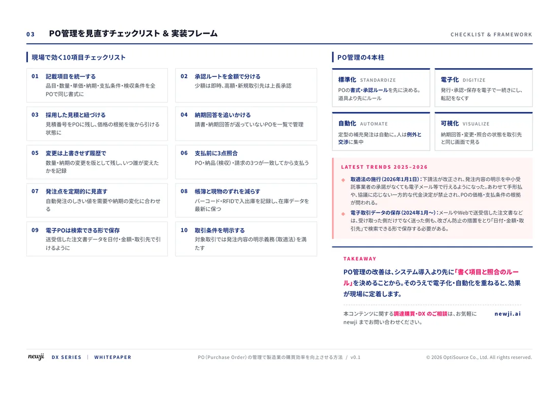
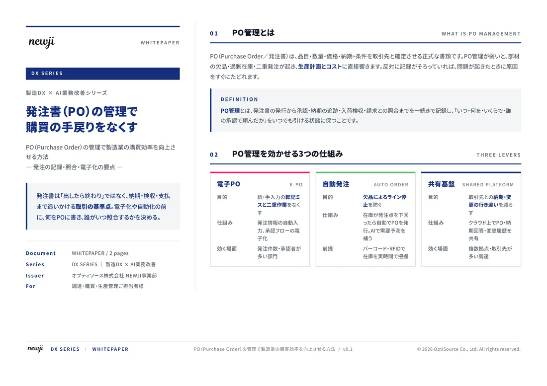
製造業の現場で使える実務資料(PDF)を無料でお届けします。"こんな資料が届きます" ↓ 下のボタンからどうぞ。
FREE DOCUMENT — サービス資料(PDF・無料)
製造業の見積・受発注クラウド
「Newji one」とは
Newji one は、製造業の調達・受発注に特化したクラウド/AIエージェント。見積依頼・発注書作成・進捗管理・承認をひとつの画面に集約し、AIが比較と異常検知を担当。最後の「GO」だけ人が押す仕組みです。
▶ 製造業の見積・受発注クラウド「Newji one」を、資料で見る(PDF・無料)
- 見積〜発注〜納期を一元管理。催促・転記のムダをゼロに
- AIが相見積もり比較と異常検知。あなたは判断だけに集中
- 取引先は「招待」で完全無料。自社コストだけで取引先ごとデジタル化
※ 取引先から招待された企業様は完全無料でご利用いただけます
関連記事




 NEWJI総研
 OEM/ODM 生産委託
 AI/DX支援
 見積・発注クラウド Newji one
受発注が増えるほど、入力・確認・催促が重くなる。
受発注管理を“仕組み化“して、ミスと工数を削減しませんか。
見積・発注・納期まで一元管理できます。