

- お役立ち記事
- Basics of “geometric tolerance”, the world standard for design and drafting, and its application to internationally error-free drawing creation
スタートアップから大手まで。
調達・受発注をAIで標準化。
相見積比較も進捗管理もAIが下支え。取引先は招待で完全無料。

Basics of “geometric tolerance”, the world standard for design and drafting, and its application to internationally error-free drawing creation

Geometric tolerance is an essential concept in the world of design and drafting, playing a crucial role in ensuring the precision and reliability of drawings used in manufacturing and engineering.
Understanding geometric tolerance is vital for creating error-free designs, especially when working on international projects where different standards and practices come into play.
This article will explore the basics of geometric tolerance, explain its importance, and discuss how it can be applied to create universally accurate and reliable drawings.
By the end, you will have a clearer understanding of how geometric tolerance serves as a world standard in design and drafting.
目次
What is Geometric Tolerance?
Geometric tolerance is a system used to define and communicate allowable variations in the shape, size, form, and orientation of a part’s features.
Unlike dimensional tolerance, which focuses solely on size, geometric tolerance considers the holistic geometry of the part, ensuring that it will function correctly under various conditions.
This approach helps in maintaining quality and consistency in manufacturing processes by providing clear guidelines on acceptable deviations from the ideal specifications.
Importance of Geometric Tolerance
Enhancing Product Quality
Geometric tolerance plays a significant role in enhancing product quality by ensuring that parts fit and function as intended.
By specifying the permissible limits of geometry, designers can minimize errors and reduce the likelihood of parts failing during assembly or operation.
Facilitating International Collaboration
In a globalized economy, products are often designed in one country, manufactured in another, and assembled in yet another.
Geometric tolerance serves as a universal language, enabling designers and manufacturers from different regions to work together effectively without miscommunication or misunderstandings.
Reducing Manufacturing Costs
By providing a clear set of guidelines, geometric tolerance helps in reducing manufacturing errors and rework, ultimately leading to cost savings.
It allows manufacturers to achieve consistent quality across all batches, minimizing waste and enhancing efficiency.
Key Elements of Geometric Tolerance
Tolerances of Form
These include straightness, flatness, circularity, and cylindricity.
Form tolerances ensure that the shape of a feature does not deviate beyond specified limits.
Tolerances of Orientation
These include angularity, perpendicularity, and parallelism.
Orientation tolerances control the angle of a feature relative to another reference, ensuring proper alignment.
Tolerances of Location
Position tolerance is a key element here, dictating the exact location of features on a part.
It ensures that holes, slots, and other features are precisely positioned as required.
Tolerances of Runout
These include circular runout and total runout tolerances.
Runout controls ensure that a surface doesn’t deviate too much when an object rotates, which is crucial for parts that involve rotational motion.
Geometric Tolerance Symbols
Geometric tolerance utilizes specific symbols to convey the requirements succinctly.
Understanding these symbols is essential for interpreting and applying geometric tolerance effectively.
Some of the common symbols include:
– Straightness: ——
– Flatness: ⊥
– Circularity: ○
– Cylindricity: ⧅
– Angularity: ∠
– Perpendicularity: ⊥
– Parallelism: ∥
– Position: ⊕
These symbols are used alongside numerical values to communicate the allowable deviation from a specified geometric feature.
Applying Geometric Tolerance in Design and Drafting
Defining the Requirements
The first step is for designers to carefully consider the functional requirements of the part and define the geometric tolerances accordingly.
This involves identifying the critical features of the part and the acceptable degree of variation.
Creating Detailed Drawings
Once the requirements are defined, designers can create detailed technical drawings that incorporate geometric tolerance symbols and values.
These drawings serve as a blueprint for manufacturing and should be as clear and precise as possible.
Ensuring Consistency with International Standards
To ensure that drawings are internationally error-free, it’s crucial to follow global standards for geometric tolerance.
Standards such as ISO 1101 are widely recognized and used, providing a consistent framework for defining and interpreting geometric tolerance across different regions.
Verification and Validation
After production, it’s important to verify that the parts meet the specified geometric tolerances.
This involves using precision measurement tools and techniques to validate the accuracy of the manufactured features.
Challenges and Best Practices
Balancing Precision and Cost
One of the challenges in applying geometric tolerance is finding the right balance between precision and cost.
Stricter tolerances can lead to higher production costs, so it’s essential to determine the most critical areas where high precision is necessary.
Continuous Learning and Adaptation
With evolving technologies and varying international standards, designers and engineers must stay updated on the latest developments in geometric tolerance practices.
Continuous learning and adaptation are key to ensuring that designs remain accurate and reliable.
Conclusion
Understanding and applying geometric tolerance is fundamental to creating high-quality, error-free drawings in the field of design and drafting.
By considering all aspects of a part’s geometry and adhering to international standards, designers can ensure that products are accurately manufactured and fit for purpose.
As a universal language, geometric tolerance facilitates effective collaboration across borders, ultimately leading to more successful and efficient global projects.
この記事の理解を深める
無料ホワイトペーパーをプレゼント
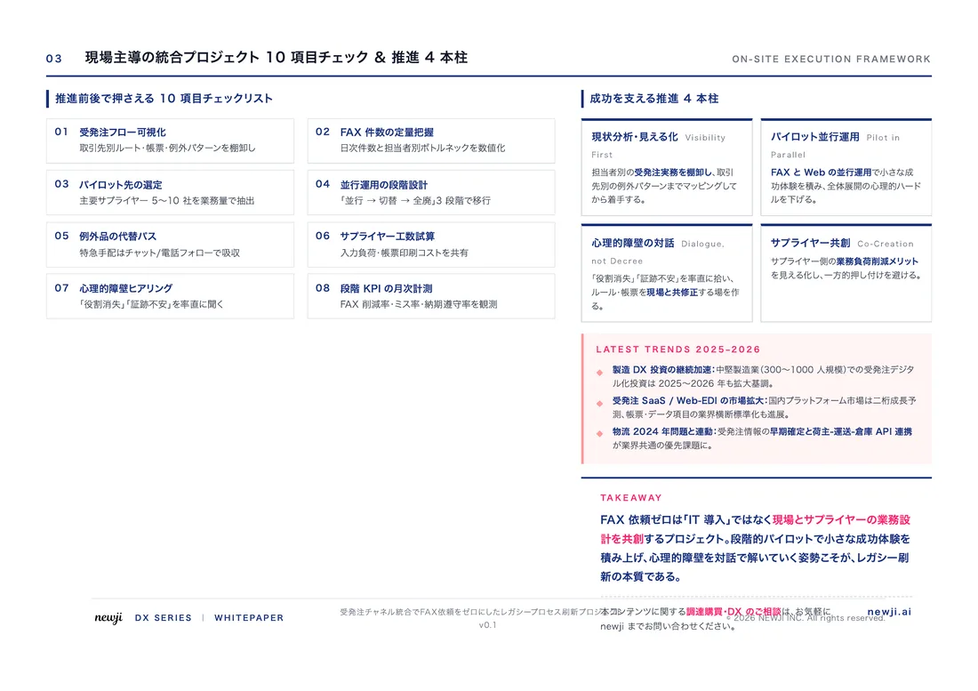
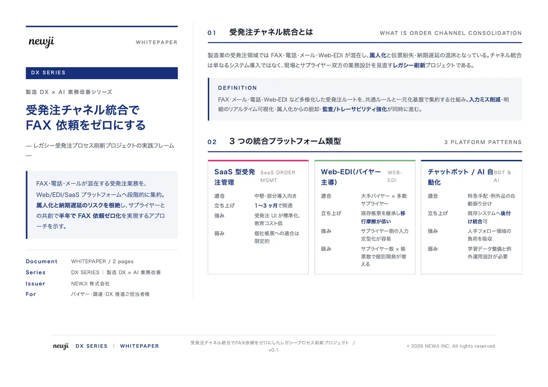
製造業の現場で使える実務資料(PDF)を無料でお届けします。"こんな資料が届きます" ↓ 下のボタンからどうぞ。
PRODUCT — 製造業向け 調達・受発注クラウド
この記事の課題、
newji で解決しませんか?
newji は、製造業の調達・受発注に特化したクラウド/AIエージェント。見積依頼・発注書作成・進捗管理・承認をひとつの画面に集約し、AIが比較と異常検知を担当。最後の「GO」だけ人が押す仕組みです。
- 見積〜発注〜納期を一元管理。催促・転記のムダをゼロに
- AIが相見積もり比較と異常検知。あなたは判断だけに集中
- 取引先は「招待」で完全無料。自社コストだけで取引先ごとデジタル化
※ 取引先から招待された企業様は完全無料でご利用いただけます


 調達購買アウトソーシング
 OEM/ODM 生産委託
 NEWJI DX
 受発注AIエージェント