

- お役立ち記事
- Points for creating “world-class mechanical drawings” using size (dimension) tolerances and geometric tolerances and how to use them correctly

その単価は妥当か。
AI が根拠付きで分析。
相見積の比較も発注も進捗管理も、ひとつの画面に。

Points for creating “world-class mechanical drawings” using size (dimension) tolerances and geometric tolerances and how to use them correctly

目次
Introduction to Mechanical Drawings
Mechanical drawings are an essential part of engineering and manufacturing.
They provide a detailed visual representation of a physical object and guide the manufacturing process.
For these drawings to be effective, they must adhere to certain standards, including the use of size (dimension) tolerances and geometric tolerances.
These tolerances ensure that the parts will fit together correctly and function as intended.
Understanding Size (Dimension) Tolerances
Size tolerances are limitations placed on the physical dimensions of a component.
They specify the acceptable range of variation that a dimension can have while still conforming to the design’s requirements.
For instance, a hole intended to be 10 mm might have a tolerance of ±0.1 mm, meaning the hole can be anywhere from 9.9 mm to 10.1 mm in diameter.
Size tolerances are crucial because they allow for minor manufacturing errors without compromising the functionality of the part.
By setting these limits, designers can reduce waste and ensure consistent quality across parts.
Types of Size Tolerances
There are generally two types of size tolerances: unilateral and bilateral.
Unilateral tolerances allow variation in only one direction, either above or below the nominal dimension.
Bilateral tolerances allow variation in both directions.
For instance, if a shaft has a nominal size of 20 mm with a unilateral tolerance of +0.05/-0 mm, it can be anywhere from 20 mm to 20.05 mm.
In contrast, a bilateral tolerance of ±0.05 mm means the shaft can range from 19.95 mm to 20.05 mm.
Selecting the appropriate type of tolerance depends on the function of the part and its interaction with other components.
Exploring Geometric Tolerances
Geometric tolerances refer to the permissible deviation of a part’s geometric characteristics.
These tolerances control the shape, location, orientation, and run-out of features in a mechanical part.
Geometric tolerances are expressed using a symbolic language standardized in engineering to communicate precise specifications.
This makes the process of quality inspection efficient and consistent.
Categories of Geometric Tolerances
There are several categories of geometric tolerances, including form, orientation, location, and run-out.
– **Form Tolerances**: These affect the shape of a feature independently of any other feature. Examples include straightness, flatness, roundness, and cylindricity.
– **Orientation Tolerances**: These control the tilt of features in relation to one another, such as parallelism, perpendicularity, and angularity.
– **Location Tolerances**: These define the position of features concerning others, such as position, concentricity, and symmetry.
– **Run-out Tolerances**: These are used to control how much one feature can turn out of place with another, typically applied to cylinders or round parts.
Implementing Tolerances in Mechanical Drawings
To create a world-class mechanical drawing with effective tolerances, engineers must carefully apply both size and geometric tolerances.
Here are some points to consider:
Assessment of Functional Requirements
The first step is to thoroughly understand the part’s functional requirements.
What is its purpose, and how does it interact with other parts?
This understanding is crucial to defining the necessary tolerances.
Application of the Right Standards
Next, use appropriate and recognized standards to apply size and geometric tolerances.
Standards like the ISO (International Organization for Standardization) or ASME (American Society of Mechanical Engineers) provide guidelines that ensure parts can be manufactured and fit properly on a global scale.
Clarity and Consistency in Dimensioning
Ensure that all dimensions and tolerances are clearly indicated on the drawing.
Use consistent units and symbols, and keep the layout of dimensions logical and easy to follow.
Balancing Precision and Cost
While precision is critical, unnecessary tight tolerances can increase production costs.
Evaluate the balance between the precision needed for functionality and the cost it adds to manufacturing.
Choose reasonable tolerances that achieve the necessary function without being excessively strict.
Utilizing Modern CAD Software
Computer-Aided Design (CAD) software provides robust tools to apply tolerances correctly in mechanical drawings.
These programs allow for precise control and adjustment, which translates into more accurate and functional designs.
Using CAD increases efficiency, reduces errors, and ensures that designs comply with the necessary standards.
Benefits of Effective Tolerance Application
Applying tolerances correctly in mechanical drawings brings numerous advantages.
It improves the reliability and durability of parts, as they are manufactured to fit and function as intended.
It reduces waste because parts are less likely to be rejected for being out of specification.
Furthermore, it enhances communication between design and manufacturing teams, ensuring that the final product meets all specifications without unnecessary iterations.
Conclusion
In summary, size and geometric tolerances are vital components of mechanical drawings.
They ensure that the parts produced will function correctly and fit together as needed.
By understanding the different types of tolerances and applying them judiciously, engineers can create world-class mechanical drawings that lead to quality and cost-effective manufacturing solutions.
Following established standards, balancing precision and cost, and leveraging modern technology are key steps to achieving precision in your designs.
この記事の理解を深める
無料ホワイトペーパーをプレゼント
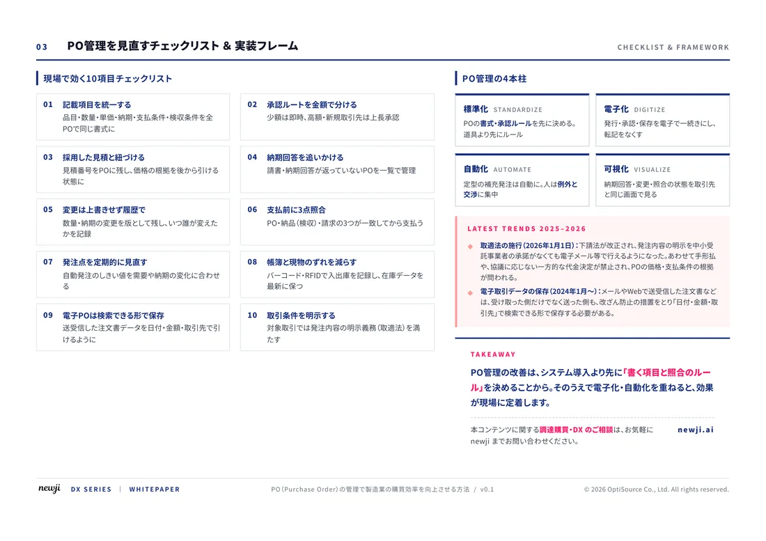
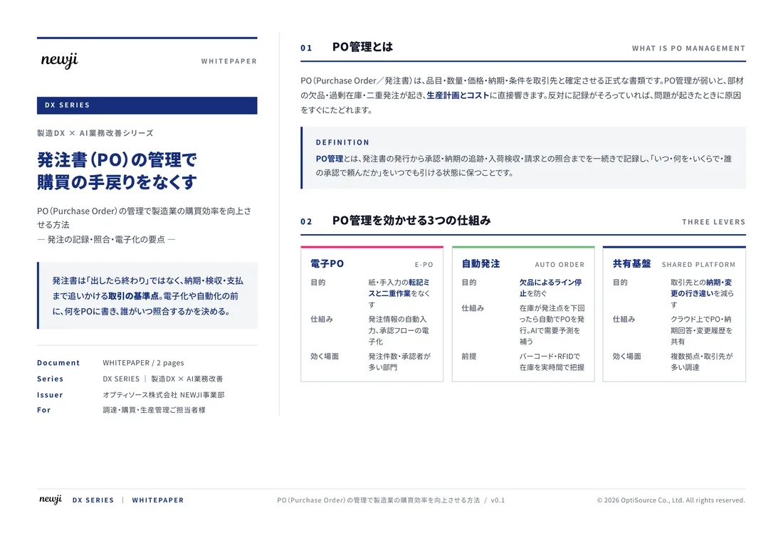
製造業の現場で使える実務資料(PDF)を無料でお届けします。"こんな資料が届きます" ↓ 下のボタンからどうぞ。
FREE DOCUMENT — サービス資料(PDF・無料)
製造業の見積・受発注クラウド
「Newji one」とは
Newji one は、製造業の調達・受発注に特化したクラウド/AIエージェント。見積依頼・発注書作成・進捗管理・承認をひとつの画面に集約し、AIが比較と異常検知を担当。最後の「GO」だけ人が押す仕組みです。
▶ 製造業の見積・受発注クラウド「Newji one」を、資料で見る(PDF・無料)
- 見積〜発注〜納期を一元管理。催促・転記のムダをゼロに
- AIが相見積もり比較と異常検知。あなたは判断だけに集中
- 取引先は「招待」で完全無料。自社コストだけで取引先ごとデジタル化
※ 取引先から招待された企業様は完全無料でご利用いただけます

 NEWJI総研
 OEM/ODM 生産委託
 AI/DX支援
 見積・発注クラウド Newji one
受発注が増えるほど、入力・確認・催促が重くなる。
受発注管理を“仕組み化“して、ミスと工数を削減しませんか。
見積・発注・納期まで一元管理できます。