

- お役立ち記事
- A practical course on the basics of size tolerance drawings that accurately convey design intentions and their application to design drawings.

その単価は妥当か。
AI が根拠付きで分析。
相見積の比較も発注も進捗管理も、ひとつの画面に。

A practical course on the basics of size tolerance drawings that accurately convey design intentions and their application to design drawings.

Understanding size tolerance drawings is crucial for anyone involved in design or engineering.
These drawings are essential for accurately conveying design intentions, ensuring that manufactured parts and components fit together as intended.
In this practical course, we will explore the basics of size tolerance drawings and their application to design drawings.
目次
What Are Size Tolerance Drawings?
Size tolerance drawings are specialized engineering diagrams that specify the allowable variations in size and geometry of a manufactured part.
These drawings ensure that parts fit together properly, function as intended, and meet quality and performance standards.
Size tolerance is a key concept in precision manufacturing where even small deviations can lead to significant issues.
The Importance of Size Tolerances
Size tolerances are important because they provide a clear language for communicating design specifications.
Without them, there would be confusion between the designer’s intent and the manufacturer’s output.
Size tolerances help prevent assembly problems, ensure interoperability of parts, and reduce wastage of material and time.
Key Concepts in Size Tolerance Drawings
Understanding size tolerance drawings involves learning several key concepts:
1. Nominal Size
The nominal size is the basic dimensional size specified on the drawing.
It represents the ideal size of a part before any tolerance is applied.
2. Tolerance Range
This is the range of allowable deviations from the nominal size.
It is typically expressed as an upper and lower limit.
3. Limits and Fits
Limits define the extreme permissible sizes of a part, while fits describe how two mating parts will align.
Common types of fits include clearance fit, interference fit, and transitional fit.
4. Geometric Dimensioning & Tolerancing (GD&T)
GD&T is a symbolic language used on engineering drawings to precisely define the geometry of parts.
It uses symbols to represent tolerances of form, orientation, location, and run-out.
How to Apply Size Tolerance to Design Drawings
Applying size tolerance to design drawings involves following systematic steps:
Step 1: Define the Design Requirements
The first step is to determine the functional requirements of the part.
Understand how the part fits into the assembly and the role it plays.
Step 2: Specify Nominal Dimensions
List the nominal dimensions for each critical feature of the part.
Include dimensions for length, width, height, diameter, etc.
Step 3: Select Suitable Tolerances
Choose appropriate tolerances based on the function of the part and the limits determined by the manufacturing process.
More critical parts may require tighter tolerances.
Step 4: Use GD&T Symbols
Apply GD&T symbols to clearly communicate the allowable variations in form, orientation, and location.
This helps in accurately conveying design intentions to the manufacturer.
Step 5: Verify and Validate the Drawing
Finally, review the drawings to ensure that they can be manufactured within the specified tolerances.
Verification might involve digital simulations or prototype testing.
Common Challenges with Size Tolerance Drawings
Despite their importance, size tolerance drawings can present challenges:
1. Misinterpretation of Tolerances
Without proper understanding, there can be errors in interpreting tolerances.
This can lead to parts not meeting design requirements.
2. Over-Tightening Tolerances
Setting overly tight tolerances can increase manufacturing costs and lead times.
It is important to balance precision with practicality.
3. Communication Issues
Miscommunication between designers, engineers, and manufacturers can lead to discrepancies in the final product.
Clear communication is essential to avoid these issues.
Best Practices for Creating Size Tolerance Drawings
1. Collaborate with Stakeholders
Work closely with the manufacturing team and other stakeholders to ensure the design is feasible and manufacturable.
2. Use Standard Tolerances
Where possible, use industry-standard tolerances to simplify the manufacturing process and reduce costs.
3. Keep Drawings Organized
Maintain a structured layout for your drawings.
Clearly label each part and include all necessary dimensions and tolerances.
4. Educate the Team
Ensure that all team members are properly trained in reading and applying size tolerance drawings.
This reduces the risk of errors and miscommunication.
Conclusion
Size tolerance drawings are an essential aspect of design and engineering, playing a crucial role in manufacturing precision parts and components.
By understanding and correctly applying these concepts, design intentions are accurately conveyed, reducing errors and ensuring efficient production.
This practical course should equip you with the fundamentals needed to make effective and accurate size tolerance drawings.
この記事の理解を深める
無料ホワイトペーパーをプレゼント
製造業の現場で使える実務資料(PDF)を無料でお届けします。"こんな資料が届きます" ↓ 下のボタンからどうぞ。
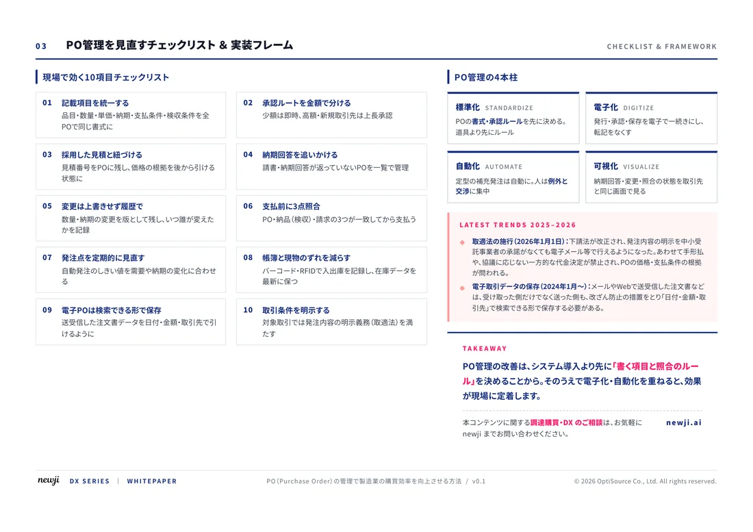
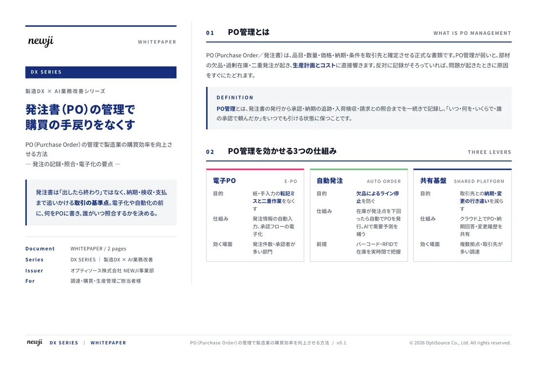
FREE DOCUMENT — サービス資料(PDF・無料)
製造業の見積・受発注クラウド
「Newji one」とは
Newji one は、製造業の調達・受発注に特化したクラウド/AIエージェント。見積依頼・発注書作成・進捗管理・承認をひとつの画面に集約し、AIが比較と異常検知を担当。最後の「GO」だけ人が押す仕組みです。
▶ 製造業の見積・受発注クラウド「Newji one」を、資料で見る(PDF・無料)
- 見積〜発注〜納期を一元管理。催促・転記のムダをゼロに
- AIが相見積もり比較と異常検知。あなたは判断だけに集中
- 取引先は「招待」で完全無料。自社コストだけで取引先ごとデジタル化
※ 取引先から招待された企業様は完全無料でご利用いただけます




 NEWJI総研
 OEM/ODM 生産委託
 AI/DX支援
 見積・発注クラウド Newji one
受発注が増えるほど、入力・確認・催促が重くなる。
受発注管理を“仕組み化“して、ミスと工数を削減しませんか。
見積・発注・納期まで一元管理できます。