

- お役立ち記事
- FEM analysis using CAE and its practical know-how

その単価は妥当か。
AI が根拠付きで分析。
相見積の比較も発注も進捗管理も、ひとつの画面に。

FEM analysis using CAE and its practical know-how

目次
Introduction to FEM Analysis and CAE
Finite Element Method (FEM) analysis is a numerical technique widely used for solving complex engineering problems.
It involves breaking down a large problem into smaller, simpler parts called finite elements.
These elements are then assembled to form a comprehensive model that can approximate various physical phenomena.
Computer-Aided Engineering (CAE) tools facilitate the process of FEM analysis.
With the help of CAE software, engineers can simulate and analyze the physical behavior of a product or system under various conditions.
This ability to predict performance, optimize designs, and reduce the need for physical prototypes makes FEM analysis extremely valuable across many industries.
The Basics of FEM Analysis
FEM works on the principle of dividing a large domain into smaller finite elements.
Each element has particular characteristics, and together they form a mesh.
The mesh acts as a framework that allows engineers to approximate a system’s behavior under stipulated conditions.
In FEM analysis, boundary conditions, material properties, and applied forces are specified within the mesh.
The method uses mathematical techniques to solve complex equations related to stress, strain, heat transfer, and other physical interactions.
Importance of Meshing
Good quality meshing is essential for accurate FEM analysis.
The mesh quality, density, and element type determine the precision of the analysis.
A finer mesh often yields more accurate results but can increase computational time and resource requirements.
Sparse or poorly defined meshes can result in inaccuracies, compromising the reliability of the FEM analysis.
Therefore, understanding how to create an optimal mesh is essential for engineers conducting FEM studies.
Boundary Conditions and Constraints
Boundary conditions describe how the model interacts with the external environment.
These conditions are crucial for setting up realistic simulations, as they define how loads and restraints act on a structure.
Boundary constraints ensure the stability of the finite element model.
They prevent rigid body motion, which could lead to errors in the simulation results.
Understanding CAE Tools for FEM Analysis
CAE tools serve as a comprehensive environment for engineers to perform FEM analysis efficiently.
These tools integrate various simulation capabilities, making it easier for professionals to conduct complex analyses.
Popular CAE Software
Several CAE software packages are preferred for FEM analysis, each offering unique features that cater to specific engineering needs.
– ANSYS: Known for comprehensive simulation capabilities across multiple physics domains, including structural, fluid, and thermal analysis.
– ABAQUS: Offers robust performance for nonlinear and dynamic simulations, often used in the automotive and aerospace industries.
– SolidWorks Simulation: Provides a user-friendly interface for performing structural, fluid flow, and thermal simulations.
Choosing the Right CAE Tools
Selecting the right CAE software depends on the specific requirements of the project.
Factors such as the complexity of the analysis, ease of use, integration capabilities, and cost considerations should influence the decision.
Engineers must also weigh the software’s ability to handle specific materials, boundary conditions, and design complexities.
Practical Applications of FEM and CAE
FEM analysis using CAE has been applied across numerous industries to solve a range of engineering problems.
Aerospace and Automotive Industries
In aerospace, FEM analysis is critical for ensuring the safety and performance of aircraft components under various flight conditions.
It helps in designing lightweight structures while maintaining strength and durability.
Similarly, the automotive industry benefits from FEM for crash simulation, aerodynamics optimization, and thermal management.
By predicting vehicle performance, manufacturers can improve safety standards and fuel efficiency.
Civil Engineering
Civil engineers utilize FEM analysis in the design of structures like bridges, buildings, and dams.
It helps in assessing load-bearing capacities, stress distribution, and the impact of environmental factors, ensuring the integrity and longevity of infrastructure.
Biomedical Engineering
In the biomedical field, FEM aids in the design of medical devices and implants.
It allows for the simulation of human body interactions, ensuring implants are safe and effective for patient care.
Best Practices for Successful FEM Analysis
Effective FEM analysis requires a combination of theoretical understanding and practical skills.
Model Simplification
Simplifying a complex model without compromising accuracy is crucial.
Unnecessary details should be removed, focusing on the aspects central to the analysis for computational efficiency.
Verification and Validation
Verification ensures the model is implemented correctly within the CAE tool, while validation confirms the model’s results align with real-world data.
Both are critical steps to establish confidence in simulation outcomes.
Collaboration and Communication
FEM analysis often involves multidisciplinary teams.
Clear communication and collaboration are necessary to incorporate different expertise and ensure seamless integration of results into the decision-making process.
Conclusion
FEM analysis using CAE has transformed engineering practices by allowing detailed simulations of complex systems.
With accurate modeling, engineers can optimize designs and improve product reliability while reducing development costs.
By understanding the principles of FEM and leveraging CAE tools effectively, industries can push the boundaries of innovation and continue to improve products and infrastructure that impact our lives daily.
この記事の理解を深める
無料ホワイトペーパーをプレゼント
製造業の現場で使える実務資料(PDF)を無料でお届けします。"こんな資料が届きます" ↓ 下のボタンからどうぞ。
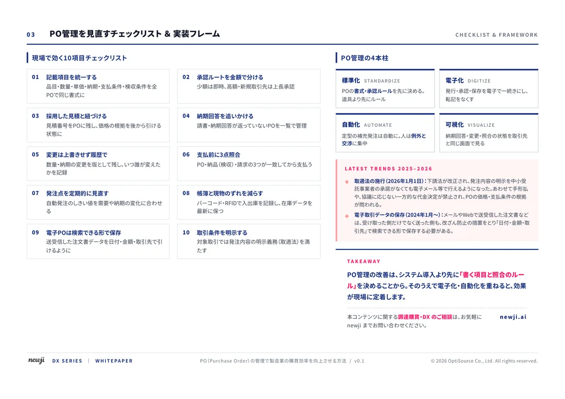
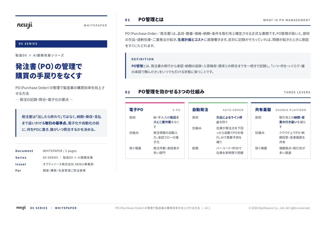
FREE DOCUMENT — サービス資料(PDF・無料)
製造業の見積・受発注クラウド
「Newji one」とは
Newji one は、製造業の調達・受発注に特化したクラウド/AIエージェント。見積依頼・発注書作成・進捗管理・承認をひとつの画面に集約し、AIが比較と異常検知を担当。最後の「GO」だけ人が押す仕組みです。
▶ 製造業の見積・受発注クラウド「Newji one」を、資料で見る(PDF・無料)
- 見積〜発注〜納期を一元管理。催促・転記のムダをゼロに
- AIが相見積もり比較と異常検知。あなたは判断だけに集中
- 取引先は「招待」で完全無料。自社コストだけで取引先ごとデジタル化
※ 取引先から招待された企業様は完全無料でご利用いただけます


 NEWJI総研
 OEM/ODM 生産委託
 AI/DX支援
 見積・発注クラウド Newji one
受発注が増えるほど、入力・確認・催促が重くなる。
受発注管理を“仕組み化“して、ミスと工数を削減しませんか。
見積・発注・納期まで一元管理できます。