

- お役立ち記事
- Fundamentals of finite element method in CAE and application to structural analysis

Fundamentals of finite element method in CAE and application to structural analysis

目次
Understanding the Basics of CAE
Computer-Aided Engineering, or CAE, is a broad field that encompasses the use of computer software to aid in engineering tasks.
These tasks can range from simulation, validation, and optimization of products and manufacturing tools.
One of the significant techniques used in CAE is the Finite Element Method (FEM).
FEM is an essential part of CAE as it allows engineers to simulate physical phenomena using mathematical models.
This technique breaks down complex structures into smaller, more manageable pieces called elements.
Because of its versatility, FEM is used in various industries, including automotive, aerospace, and civil engineering.
What is the Finite Element Method?
The Finite Element Method is a numerical technique for solving problems in engineering and mathematical physics.
It is particularly useful for problems where the geometry is complicated, material properties are complex, and where the physical loading conditions are challenging.
In FEM, an object is divided into a finite number of sub-units or ‘elements.’
These elements are interconnected at points called nodes.
Each node is associated with one or more unknown parameters, such as displacement.
The behavior of the nodes can be used to understand how the whole structure behaves.
Historical Development of FEM
FEM originated from the need to solve complex elasticity and structural analysis problems in civil and aeronautical engineering.
The method initially gained traction in the 1950s through the work of engineers like Ray Clough.
Over the subsequent decades, advancements in computer technology have allowed FEM techniques to become even more sophisticated and widely applicable.
How FEM Works
To perform an analysis using FEM, the first step is to create a geometric representation of the structure.
This representation is then used to generate a finite element model that incorporates the material properties, boundary conditions, and applied loads.
Once the model is set up, it is discretized into elements and nodes.
The behavior of these elements is governed by differential equations, which are then converted into algebraic equations using numerical methods.
These equations are assembled into a larger system that represents the entire structure.
Solving this system of equations provides the values of unknown parameters at each node, which helps predict the structure’s response to external influences.
Mesh Generation
A crucial aspect of FEM is mesh generation, which involves dividing the geometry into smaller elements.
The quality of the mesh can significantly impact the accuracy of the results.
A finer mesh, with smaller elements, generally produces more accurate results but requires more computational resources.
Material Properties and Boundary Conditions
Another critical component of FEM analysis is defining material properties and boundary conditions.
Material properties include characteristics such as elasticity, density, and thermal conductivity.
Boundary conditions specify how the model is constrained or loaded, influencing how the simulated structure behaves under different scenarios.
Applications of FEM in Structural Analysis
FEM is particularly powerful in structural analysis, which involves evaluating the strength and stability of structures under various loads.
This application is vital in multiple fields, including the design of bridges, buildings, aircraft, and automobiles.
Stress and Strain Analysis
One of the primary uses of FEM in structural analysis is stress and strain analysis.
Engineers use FEM to predict how a structure will react to external loads, such as forces or pressures.
By understanding these reactions, engineers can design structures that are safe and efficient, ensuring they can withstand anticipated loads without failure.
Dynamic Analysis
Dynamic analysis is another area where FEM is extensively used.
This type of analysis is crucial for structures subject to dynamic loads, such as earthquakes or impacts.
By simulating how these dynamic loads affect structures, FEM helps engineers design buildings and other constructions that can resist such forces, thereby protecting lives and maintaining structural integrity.
Thermal Analysis
FEM is also used for thermal analysis, which examines how structures respond to temperature changes.
This is particularly important in fields like electronics and aerospace, where thermal management is critical for system performance and reliability.
Advantages of Using FEM
There are several advantages to using FEM in CAE, particularly in structural analysis.
Precision and Flexibility
FEM allows for precise modeling of complex geometries and material properties.
It provides flexibility in testing various design scenarios and modifications without requiring physical prototypes.
Cost-Effectiveness
While setting up FEM models requires computational resources, it is often more cost-effective than traditional testing methods.
This reduces the need for building multiple prototypes, saving both time and money.
Challenges and Considerations
Despite its advantages, FEM also has its challenges.
Building accurate and reliable models can be time-consuming and requires a good understanding of the physics and mathematics involved.
Moreover, the solutions to FEM models can sometimes be computationally expensive, requiring significant processing power and memory.
Conclusion
The Finite Element Method is integral to modern engineering, providing critical insights into the behavior of structures under various conditions.
While there are challenges in its application, the benefits, such as precision and cost-effectiveness, make it an invaluable tool in the engineering domain.
As technology advances, the capabilities and applications of FEM in CAE will continue to expand, driving innovations across industries.
この記事の理解を深める
無料ホワイトペーパーをプレゼント
製造業の現場で使える実務資料(PDF)を無料でお届けします。"こんな資料が届きます" ↓ 下のボタンからどうぞ。
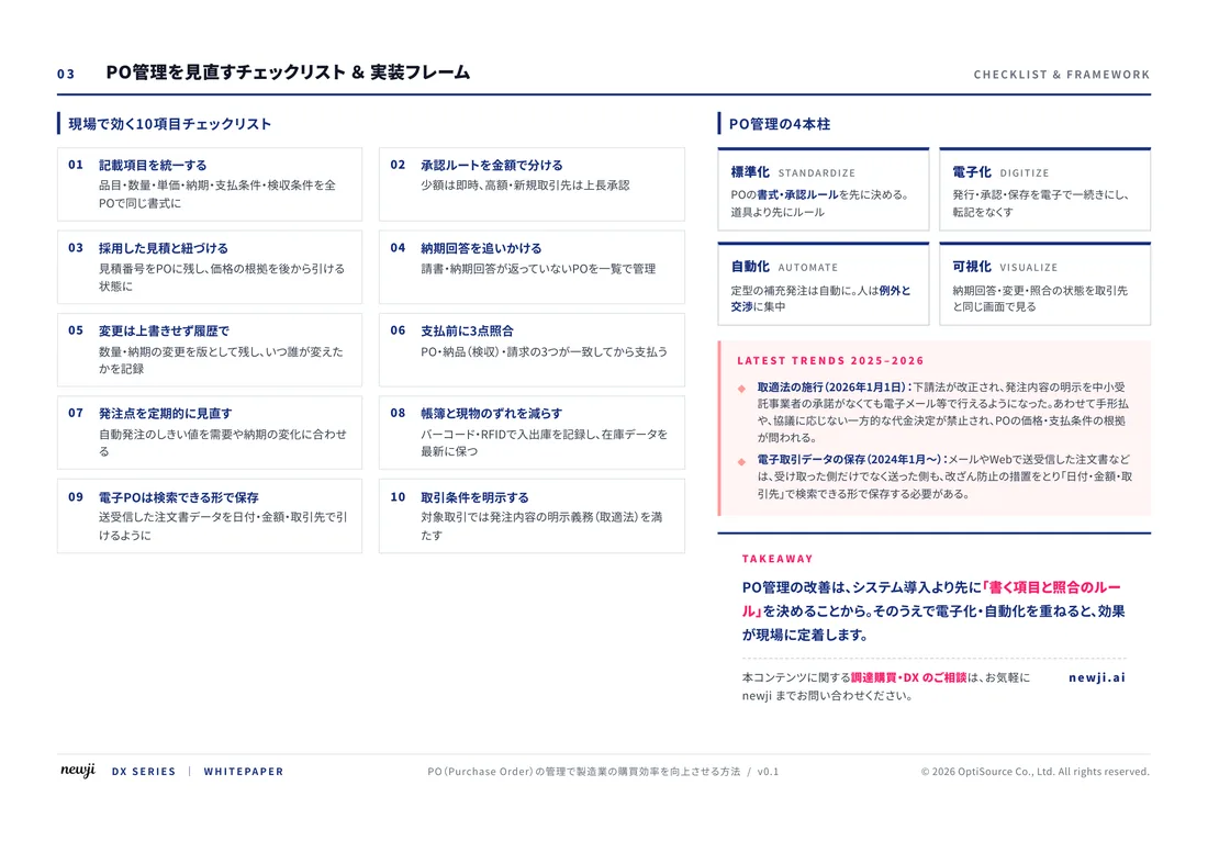
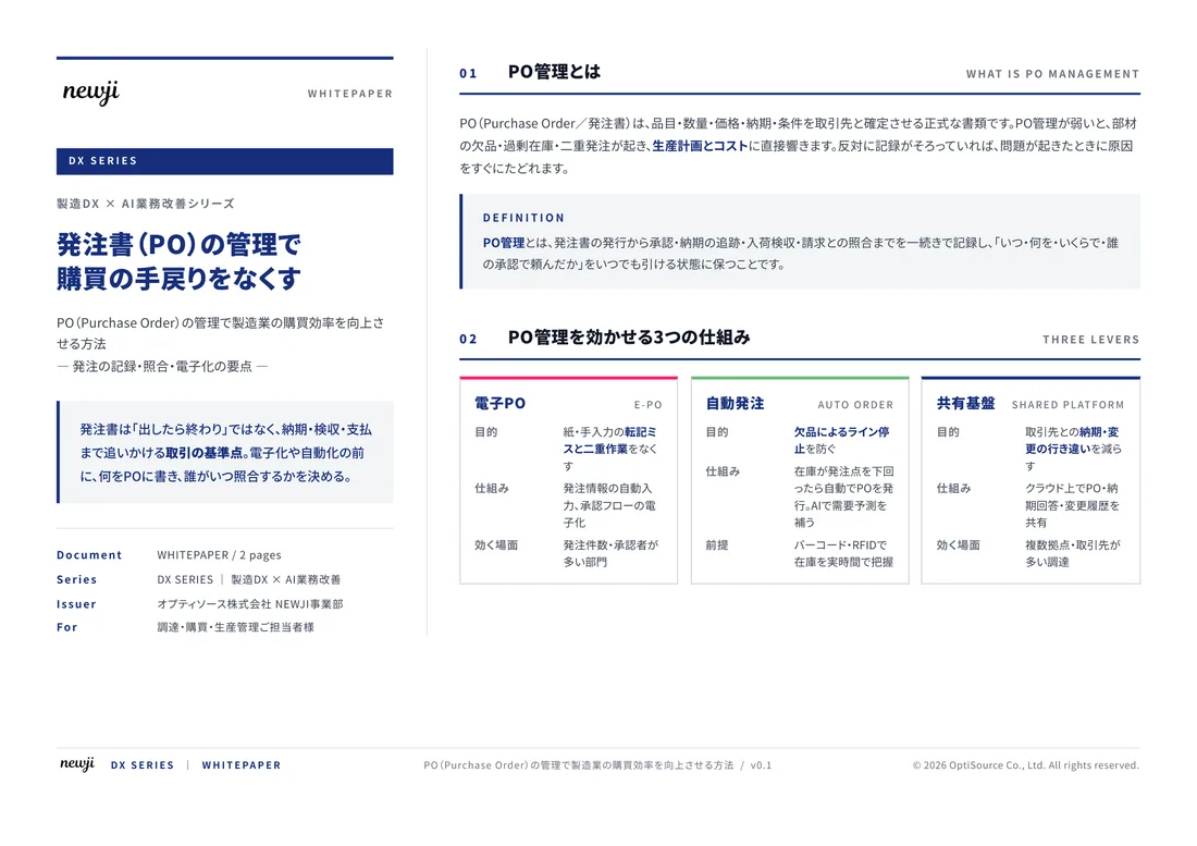
FREE DOCUMENT — サービス資料(PDF・無料)
製造業の見積・受発注クラウド
「Newji one」とは
Newji one は、製造業の調達・受発注に特化したクラウド/AIエージェント。見積依頼・発注書作成・進捗管理・承認をひとつの画面に集約し、AIが比較と異常検知を担当。最後の「GO」だけ人が押す仕組みです。
▶ 製造業の見積・受発注クラウド「Newji one」を、資料で見る(PDF・無料)
- 見積〜発注〜納期を一元管理。催促・転記のムダをゼロに
- AIが相見積もり比較と異常検知。あなたは判断だけに集中
- 取引先は「招待」で完全無料。自社コストだけで取引先ごとデジタル化
※ 取引先から招待された企業様は完全無料でご利用いただけます


 NEWJI総研
 OEM/ODM 生産委託
 AI/DX支援
 見積・発注クラウド Newji one
受発注が増えるほど、入力・確認・催促が重くなる。
受発注管理を“仕組み化“して、ミスと工数を削減しませんか。
見積・発注・納期まで一元管理できます。