

- お役立ち記事
- Fundamentals of mechanical drawing and geometric tolerances and how to effectively apply them in practice

その単価は妥当か。
AI が根拠付きで分析。
相見積の比較も発注も進捗管理も、ひとつの画面に。

Fundamentals of mechanical drawing and geometric tolerances and how to effectively apply them in practice

Mechanical drawing is a vital skill in the fields of engineering and manufacturing.
It involves creating detailed and accurate representations of objects, which are used as guides for production or construction.
Understanding geometric tolerances is an essential aspect of this process, as they dictate the acceptable range of variation in a physical object’s form or location.
目次
What is Mechanical Drawing?
Mechanical drawing, also known as drafting, is the process of creating detailed diagrams of mechanical components or systems.
These drawings are essential in communicating how a part or machine should be fabricated.
Mechanical drawings typically include dimensions, materials, and specifications needed for manufacturing.
Traditionally, mechanical drawings were made by hand using pencils, rulers, and compasses.
Today, most mechanical drawings are created using computer-aided design (CAD) software, which provides precision and allows for easy modifications.
Components of a Mechanical Drawing
A typical mechanical drawing consists of several key elements:
– **Title Block**: This section provides information about the drawing, such as the name of the part, the creator’s name, and the date.
– **Views**: These include front, top, and side views, offering different perspectives on the object.
– **Dimensioning**: This is crucial, as it provides the exact measurements needed for fabrication.
– **Annotations**: These include notes and labels that provide additional information about the part.
Introduction to Geometric Tolerances
Geometric tolerances define the permissible limits or boundaries of variation in a physical object’s geometry.
They ensure that even when parts are manufactured under the allowable tolerances, they will function correctly in assembly and operation.
Types of Geometric Tolerances
There are several types of geometric tolerances, each serving a specific purpose:
– **Form Tolerances**: These include flatness, straightness, roundness, and cylindricity.
Form tolerances control the shape of individual features.
– **Orientation Tolerances**: These include parallelism, perpendicularity, and angularity.
Orientation tolerances specify the orientation of features concerning each other.
– **Location Tolerances**: These include position, concentricity, and symmetry.
They control the location of features relative to one another.
– **Runout Tolerances**: These include runout and total runout.
Runout tolerances control the surfaces’ variation as they revolve.
Benefits of Geometric Tolerances
– **Precision**: They allow for tight control over manufacturing processes, improving precision.
– **Interchangeability**: Ensures that parts will fit together properly across different production runs.
– **Cost-Effectiveness**: Reducing scrap and rework by setting acceptable limits on part variations.
Applying Geometric Tolerances Effectively
To effectively apply geometric tolerances in mechanical drawings, several strategies can be employed:
Understand the Functionality
Before applying tolerances, it’s crucial to fully understand the part’s functionality and how it interacts with other components.
This knowledge helps in determining which tolerances are critical and which can be more lenient.
Use Datums Effectively
Datums are reference points, lines, or surfaces on a part.
They are crucial in defining geometric tolerances, as they serve as the references from which measurements are taken.
Careful selection of datums is essential for ensuring precision.
Simplify Where Possible
Overly complex tolerances can lead to misinterpretation and unnecessary manufacturing costs.
Whenever possible, simplify the tolerance scheme while maintaining the necessary functionality.
Think About the Manufacturing Process
Consider the capabilities and limitations of the manufacturing process when specifying tolerances.
Ensure that the tolerances can be realistically achieved with the available equipment and processes.
Communicate Clearly
Clear communication is critical.
Ensure that the mechanical drawings and tolerance specifications are easy to interpret and leave no room for ambiguity.
Conclusion
Mechanical drawing and geometric tolerances are fundamental aspects of engineering and manufacturing.
They ensure that parts and assemblies are manufactured accurately, meet design specifications, and perform as intended.
By understanding the basics of mechanical drawing and effectively applying geometric tolerances, engineers can enhance the quality and reliability of their designs.
この記事の理解を深める
無料ホワイトペーパーをプレゼント
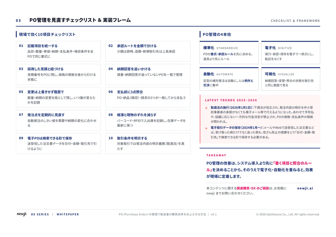
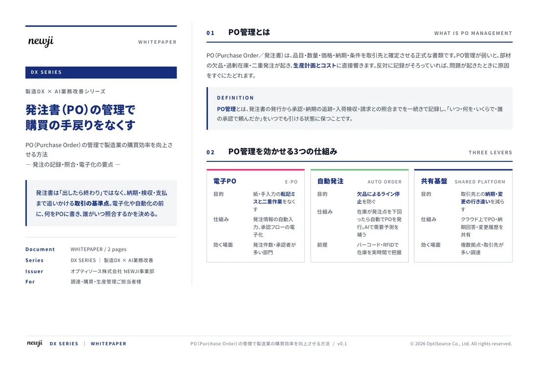
製造業の現場で使える実務資料(PDF)を無料でお届けします。"こんな資料が届きます" ↓ 下のボタンからどうぞ。
FREE DOCUMENT — サービス資料(PDF・無料)
製造業の見積・受発注クラウド
「Newji one」とは
Newji one は、製造業の調達・受発注に特化したクラウド/AIエージェント。見積依頼・発注書作成・進捗管理・承認をひとつの画面に集約し、AIが比較と異常検知を担当。最後の「GO」だけ人が押す仕組みです。
▶ 製造業の見積・受発注クラウド「Newji one」を、資料で見る(PDF・無料)
- 見積〜発注〜納期を一元管理。催促・転記のムダをゼロに
- AIが相見積もり比較と異常検知。あなたは判断だけに集中
- 取引先は「招待」で完全無料。自社コストだけで取引先ごとデジタル化
※ 取引先から招待された企業様は完全無料でご利用いただけます

 NEWJI総研
 OEM/ODM 生産委託
 AI/DX支援
 見積・発注クラウド Newji one
受発注が増えるほど、入力・確認・催促が重くなる。
受発注管理を“仕組み化“して、ミスと工数を削減しませんか。
見積・発注・納期まで一元管理できます。