
- お役立ち記事
- Geometric tolerance symbols Meaning Maximum material state Tolerance area Function Gauge Geometric tolerance measurement Drawing reading exercise

その単価は妥当か。
AI が根拠付きで分析。
相見積の比較も発注も進捗管理も、ひとつの画面に。

Geometric tolerance symbols Meaning Maximum material state Tolerance area Function Gauge Geometric tolerance measurement Drawing reading exercise

Geometric tolerancing can be seen as the language of engineering blueprints.
It is a system that standardizes the communication of design intent and ensures that parts fit together perfectly in a mechanical system.
Understanding geometric tolerance symbols, their meanings, and their application in maximum material conditions are essential in creating functional and efficient designs.
This guide will explore the concepts of geometric tolerance, tolerance zones, maximum material condition (MMC), functional gauge design, geometric tolerance measurement, and how to read engineering drawings.
目次
Understanding Geometric Tolerance Symbols
Geometric tolerance symbols are used within an engineering drawing to specify dimensions and tolerances.
These symbols guide the manufacturing process, ensuring that the components fit correctly and function as intended.
Each symbol represents a different type of tolerance, such as position, flatness, roundness, cylindricity, and more.
A few of the most common geometric tolerance symbols include:
– **Flatness**: Ensures a surface is flat within specified limits.
– **Straightness**: Indicate that a feature must be straight within a tolerance zone.
– **Roundness**: Ensures that every cross-section of a cylinder or sphere is round within a specified tolerance.
– **Cylindricity**: A 3D version of roundness, ensuring a cylinder or cone is entirely in tolerance.
– **Position**: Specifies the allowable deviation for the location of a feature from its true location.
Maximum Material Condition (MMC)
The maximum material condition (MMC) is a critical concept in geometric tolerancing.
This term is used to describe the condition of a part when it contains the greatest amount of material yet remains within its dimensional limits.
For instance, in the case of a hole, the MMC would be its smallest permissible diameter because this means the hole is as small as it can be, leaving the most material around it.
Conversely, for a shaft, the MMC is its largest permissible diameter.
Applying MMC allows engineers to create designs that account for material variations and ensure that components can be easily manufactured and assembled.
When the MMC is used in conjunction with a particular tolerance, it lets manufacturers produce parts that fit together more consistently.
Tolerance Zones
Tolerance zones define the acceptable variation for a given geometric feature.
They are depicted on engineering drawings using dimensions and geometric symbols and typically allow for some form of error or deviation without compromising the part’s function.
These zones are essential for maintaining the interchangeable nature of parts in mechanical engineering and manufacturing.
Geometric tolerance zones are often represented in two- or three-dimensional spaces, depending on the feature being controlled.
For example:
– A flatness tolerance might use a two-dimensional zone, ensuring that a surface lies between two parallel planes.
– A cylindricity tolerance would apply a three-dimensional zone, requiring that the surface of a component falls within a cylindrical shell.
Understanding tolerance zones is vital for producing components that operate seamlessly in their intended applications.
Functional Gauges
Functional gauges are tools designed to test whether a manufactured part meets its designed geometric and dimensional requirements.
These gauges are configured to mirror the shape specified in the technical drawing, noticeable in the features’ tolerance zone.
Functional gauges are used before parts are approved for assembly, helping identify out-of-spec parts that might compromise mechanical performance.
These gauges improve manufacturing efficiency by providing fast, reliable, and straightforward checks.
By using a physical replica of the tolerance zone, manufacturers can quickly confirm if the parts meet specifications by gauging whether they fit within the designed dimensions.
Geometric Tolerance Measurement
Measuring geometric tolerance involves confirming that parts meet the specified dimensions and geometric accuracy.
This process is crucial for quality control, ensuring parts are produced within acceptable limits.
The measurement can be divided into:
1. **Dimensional measurement**: Using tools like micrometers and calipers for precise linear dimensions.
2. **Geometric measurement**: Instruments such as Coordinate Measuring Machines (CMMs) measure the intricate shapes and contours of a component.
The measurement process must account for potential errors and be executed under controlled conditions to yield reliable results.
Adopting advanced measurement technology like laser scanning can provide superior accuracy and speed over traditional methods.
Reading Engineering Drawings
Reading engineering drawings is a vital skill for engineers, designers, and manufacturers.
These drawings convey all the necessary information, including dimensions, materials, tolerances, and specifications, to create a part.
Understanding how to interpret geometric symbols and tolerance information is essential for ensuring design accuracy.
When reading an engineering drawing:
– Start by identifying the datum, which serves as a reference point in the drawing.
– Examine the tolerance symbols and their corresponding values.
– Follow the sequence of features to understand the part structure.
– Check the scale and units to ensure accurate interpretation of dimensions.
– Consult the drawing’s legend or notes for additional information.
Integrating knowledge about maximum material conditions, tolerance zones, functional gauges, geometric tolerance measurement, and reading engineering drawings will enhance your ability to design and manufacture high-quality components.
Understanding these key elements will enable you to create parts that fit together seamlessly, provide operational efficiency, and maintain reliability in any mechanical system.
この記事の理解を深める
無料ホワイトペーパーをプレゼント
製造業の現場で使える実務資料(PDF)を無料でお届けします。"こんな資料が届きます" ↓ 下のボタンからどうぞ。
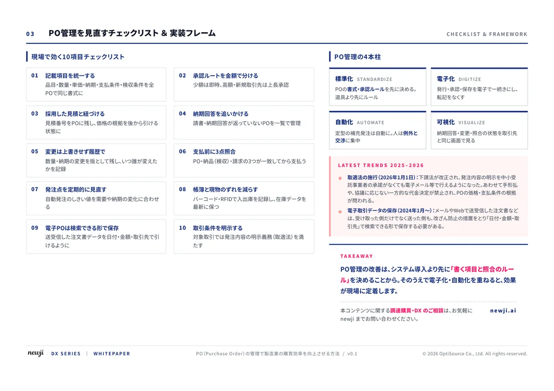
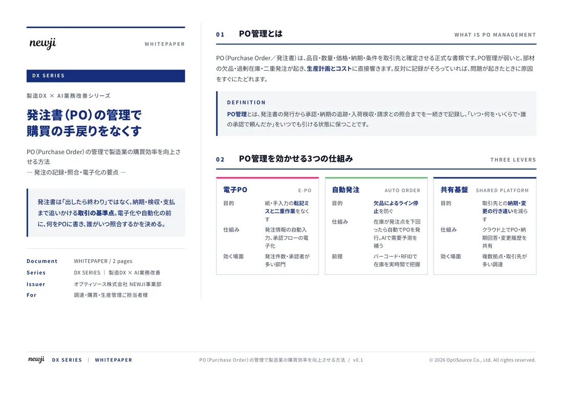
FREE DOCUMENT — サービス資料(PDF・無料)
製造業の見積・受発注クラウド
「Newji one」とは
Newji one は、製造業の調達・受発注に特化したクラウド/AIエージェント。見積依頼・発注書作成・進捗管理・承認をひとつの画面に集約し、AIが比較と異常検知を担当。最後の「GO」だけ人が押す仕組みです。
▶ 製造業の見積・受発注クラウド「Newji one」を、資料で見る(PDF・無料)
- 見積〜発注〜納期を一元管理。催促・転記のムダをゼロに
- AIが相見積もり比較と異常検知。あなたは判断だけに集中
- 取引先は「招待」で完全無料。自社コストだけで取引先ごとデジタル化
※ 取引先から招待された企業様は完全無料でご利用いただけます




 NEWJI総研
 OEM/ODM 生産委託
 AI/DX支援
 見積・発注クラウド Newji one
受発注が増えるほど、入力・確認・催促が重くなる。
受発注管理を“仕組み化“して、ミスと工数を削減しませんか。
見積・発注・納期まで一元管理できます。