

- お役立ち記事
- How to use CAE for thermal fluid analysis

その単価は妥当か。
AI が根拠付きで分析。
相見積の比較も発注も進捗管理も、ひとつの画面に。

How to use CAE for thermal fluid analysis

目次
Understanding Thermal Fluid Analysis
Thermal fluid analysis is a crucial aspect of many engineering applications where heat transfer and fluid flow play significant roles.
In industries such as automotive, aerospace, electronics, and energy, understanding how heat and fluids interact can significantly impact the design and functionality of products and systems.
Computer-aided engineering (CAE) tools have revolutionized the way engineers approach thermal fluid analysis, providing detailed insights that guide design decisions.
In simple terms, thermal fluid analysis involves studying the behavior of fluids under thermal stresses to understand their impact on system performance.
The goal is to predict how fluids, such as air or liquids, will move under given conditions, and how they will transfer heat within a system.
This understanding helps engineers optimize designs for efficiency, safety, and reliability.
What is CAE in Thermal Fluid Analysis?
CAE tools are software applications that simulate the physical processes occurring in a system.
For thermal fluid analysis, CAE tools model the heat transfer and fluid dynamics to predict how a system will behave under different conditions.
These tools make it possible to visualize heat distribution, fluid flow paths, and potential problem areas without the need for physical prototypes.
The use of CAE in thermal fluid analysis provides several advantages.
It reduces the time and cost associated with physical testing, allows for rapid iteration of design changes, and offers the ability to analyze complex systems in a way that isn’t possible with simple analytical calculations or empirical testing alone.
Steps to Using CAE for Thermal Fluid Analysis
1. Define the Problem
The first step in any CAE analysis is to clearly define the problem.
This involves identifying the objectives of the analysis, the system or component to be studied, the operating conditions, and any constraints or limitations.
Understanding the scope of the problem helps in selecting the appropriate CAE tool and simulation methodology.
2. Create a Geometric Model
Once the problem is defined, the next step is to create a geometric model of the system.
This model is typically developed using computer-aided design (CAD) software and serves as the foundation for simulation.
The geometry must accurately represent the physical system, including all components that influence thermal and fluid behavior.
3. Mesh Generation
The geometric model is then divided into smaller, discrete elements using a process called meshing.
The mesh determines how the fluid and temperature fields are computed; finer meshes provide more detailed results but require more computational resources.
The quality of the mesh can significantly affect the accuracy of the simulation, so careful consideration is necessary to balance resolution and computational efficiency.
4. Define Boundary Conditions
Boundary conditions define how the simulation interacts with the model’s environment.
This includes specifying inputs such as temperature, pressure, and fluid velocity at various locations within the model.
Properly setting boundary conditions is essential as they determine how energy and mass enter, exit, and interact within the system.
5. Set Material Properties
Assigning material properties is a critical step in thermal fluid analysis.
Different materials conduct heat and react to stress differently, and these properties need to be accurately represented in the simulation.
Commonly needed material properties include thermal conductivity, specific heat, and viscosity for fluids.
6. Run the Simulation
With the model prepared, boundary conditions applied, and material properties assigned, the simulation can be run.
CAE software uses mathematical algorithms to solve conservation equations for mass, momentum, and energy within the system.
Depending on the complexity of the model, simulations can range from minutes to days to complete.
7. Analyze Results
After running the simulation, the results must be analyzed to gain insights into the system’s behavior.
CAE tools often provide results in the form of temperature distributions, fluid flow vectors, pressure contours, and other visualizations.
These results can help identify hot spots, optimize fluid flow, and improve overall system performance.
8. Validate with Physical Data
Although CAE provides powerful predictions, it’s crucial to validate simulation results against physical data or experimental measurements where possible.
This step ensures that the model accurately represents real-world behavior, which increases confidence in the design and subsequent iterations.
Benefits of Using CAE for Thermal Fluid Analysis
The integration of CAE tools in thermal fluid analysis offers multiple benefits.
It allows for more efficient and effective design processes by identifying potential issues early on.
This can lead to significant cost savings by reducing the need for multiple prototypes and extensive physical testing.
Additionally, CAE allows engineers to explore more design options and optimizations than would be feasible through experimental methods alone.
It provides a controlled environment to test extreme operating conditions, which might be dangerous or impractical to replicate in real life.
Challenges and Considerations
While CAE tools provide powerful capabilities for thermal fluid analysis, they also come with challenges.
Simulations require high levels of expertise to ensure accurate setup and interpretation of results.
Moreover, complex simulations can be computationally intensive, often requiring access to high-performance computing resources.
It’s essential for engineers to understand the limitations of their CAE tools, including approximations and assumptions made in the simulation models.
A solid foundation in the fundamentals of heat transfer and fluid dynamics is necessary to make informed decisions throughout the analysis process.
Conclusion
Using CAE for thermal fluid analysis is a transformative approach in engineering that enhances the ability to design efficient and reliable systems.
With careful model setup and validation, CAE tools provide insights that drive innovation and improve system performance across a range of industries.
As technology continues to advance, the role of CAE in thermal fluid analysis will only become more integral in engineering design processes.
この記事の理解を深める
無料ホワイトペーパーをプレゼント
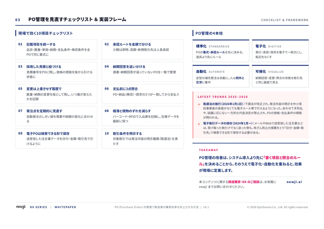
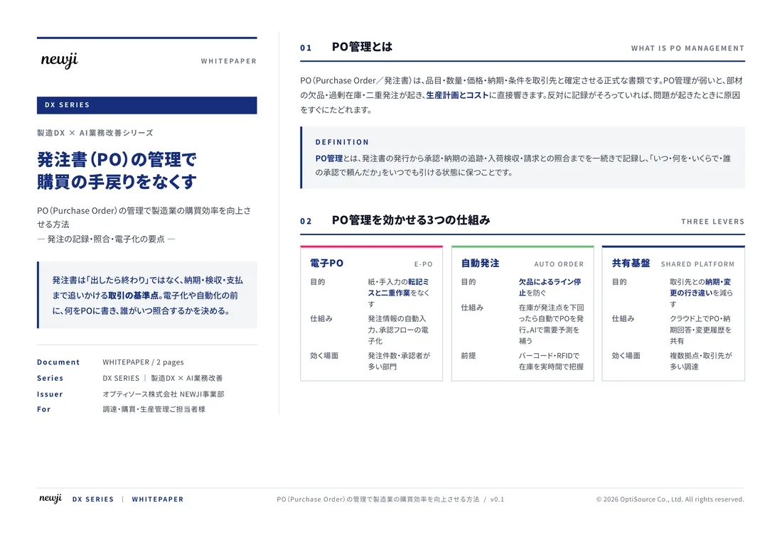
製造業の現場で使える実務資料(PDF)を無料でお届けします。"こんな資料が届きます" ↓ 下のボタンからどうぞ。
FREE DOCUMENT — サービス資料(PDF・無料)
製造業の見積・受発注クラウド
「Newji one」とは
Newji one は、製造業の調達・受発注に特化したクラウド/AIエージェント。見積依頼・発注書作成・進捗管理・承認をひとつの画面に集約し、AIが比較と異常検知を担当。最後の「GO」だけ人が押す仕組みです。
▶ 製造業の見積・受発注クラウド「Newji one」を、資料で見る(PDF・無料)
- 見積〜発注〜納期を一元管理。催促・転記のムダをゼロに
- AIが相見積もり比較と異常検知。あなたは判断だけに集中
- 取引先は「招待」で完全無料。自社コストだけで取引先ごとデジタル化
※ 取引先から招待された企業様は完全無料でご利用いただけます


 NEWJI総研
 OEM/ODM 生産委託
 AI/DX支援
 見積・発注クラウド Newji one
受発注が増えるほど、入力・確認・催促が重くなる。
受発注管理を“仕組み化“して、ミスと工数を削減しませんか。
見積・発注・納期まで一元管理できます。