
- お役立ち記事
- The basics of “geometric tolerances” that accurately convey the designer’s intentions and how to utilize them in drawings

その単価は妥当か。
AI が根拠付きで分析。
相見積の比較も発注も進捗管理も、ひとつの画面に。

The basics of “geometric tolerances” that accurately convey the designer’s intentions and how to utilize them in drawings

Geometric tolerances are a fundamental aspect of engineering drawings, providing a clear and concise way to communicate the designer’s intent regarding the allowable variations in part geometry. Understanding geometric tolerances is essential for engineers, manufacturers, and quality control professionals to ensure that parts fit together correctly and function as intended. In this article, we’ll delve into the basics of geometric tolerances and how they can be effectively utilized in drawings.
目次
What Are Geometric Tolerances?
Geometric tolerances define the permissible limits of variation in a part’s geometry. Unlike dimensional tolerances, which specify allowable size variations, geometric tolerances address the shape, orientation, and position of features. This includes characteristics such as flatness, straightness, roundness, and angularity.
The purpose of using geometric tolerances is to ensure that parts will fit together properly in an assembly, function as designed, and be interchangeable without problems. These tolerances are specified in the form of symbols on engineering drawings, providing a universal language that simplifies communication between designers, manufacturers, and inspectors.
Why Use Geometric Tolerances?
Geometric tolerances offer several advantages over traditional dimensional tolerancing:
1. **Improved Clarity**: Geometric tolerances can express complex tolerance requirements more clearly and succinctly than linear dimensions alone.
2. **Functional Focus**: By specifying geometric tolerances, designers can focus on the functional aspects of a part, ensuring it will work correctly in its intended application.
3. **Interchangeability**: Correctly specified geometric tolerances help ensure parts are interchangeable, even when produced by different manufacturers.
4. **Quality Assurance**: These tolerances allow for more precise quality control and inspection, reducing the risk of assembly issues.
Key Concepts in Geometric Tolerancing
Some fundamental concepts lay the groundwork for understanding geometric tolerances:
Datums
Datums serve as reference points or surfaces on a part from which measurements are taken. They provide the starting point for defining geometric tolerances and are essential for ensuring consistency in measurements.
Symbols
Geometric tolerances use a variety of symbols to represent different types of tolerances. For instance, a straightness tolerance might be represented by a straight line, while flatness would use a parallelogram. Other common symbols include circles for roundness and angles for angularity.
Feature Control Frame
The feature control frame is a standardized way to communicate geometric tolerances on a drawing. It contains symbols indicating the type of tolerance, the tolerance value, and any applicable datum references. Understanding how to read and interpret this frame is crucial for working with geometric tolerances.
Common Types of Geometric Tolerances
Here’s a closer look at some of the most common geometric tolerances you’ll encounter:
Form Tolerances
Form tolerances control the shape of a feature. Common form tolerances include:
– **Flatness**: Ensures a surface is even without peaks or valleys.
– **Straightness**: Ensures that a line element is straight along its entire length.
– **Roundness**: This tolerance controls the roundness or circularity of a feature.
Orientation Tolerances
Orientation tolerances specify the tilt of a feature:
– **Angularity**: Controls how a surface or axis is slanted relative to a datum.
– **Perpendicularity**: Ensures that a feature is at a right angle to a datum.
– **Parallelism**: Ensures that surfaces or axes are parallel to a datum.
Location Tolerances
Location tolerances manage the positioning of features:
– **Position**: Controls the location of a feature relative to datums.
– **Concentricity**: Ensures the central axes of features are aligned.
Runout Tolerances
Runout tolerances deal with the variation when a part rotates:
– **Circular Runout**: Limits variation in a single circle during rotation.
– **Total Runout**: Manages variation throughout the entire rotated surface or feature.
Implementing Geometric Tolerances in Drawings
To effectively use geometric tolerances in drawings, follow these steps:
1. Define the Part’s Features
Start by identifying the critical features of the part that require tolerance control. This might include surfaces that must be flat or axes that need precise positioning.
2. Select Appropriate Tolerances
Choose the appropriate geometric tolerances that align with the part’s functional requirements. Consider form, orientation, location, and runout tolerances as necessary.
3. Establish Datums
Identify suitable datums that will serve as reference points for measurements. Datums must be stable and repeatable to ensure consistent inspection results.
4. Create Feature Control Frames
Use feature control frames to communicate the selected tolerances on the drawing clearly. Ensure each frame includes the tolerance symbol, value, and any applicable datum references.
5. Collaborate with Team Members
Discuss the drawing with other stakeholders, including manufacturing and quality control teams, to ensure that the tolerances are understood and feasible.
Conclusion
Geometric tolerances play a critical role in manufacturing and engineering, providing a standardized method for communicating complex geometric requirements. By accurately implementing these tolerances in drawings, designers can ensure parts function properly, assemblies fit together seamlessly, and products meet quality standards.
Understanding and utilizing geometric tolerances effectively requires a grasp of their symbols, types, and applications. With this knowledge, stakeholders across design, manufacturing, and quality control can collaborate to produce high-quality, functional products that meet or exceed expectations.
この記事の理解を深める
無料ホワイトペーパーをプレゼント
製造業の現場で使える実務資料(PDF)を無料でお届けします。"こんな資料が届きます" ↓ 下のボタンからどうぞ。
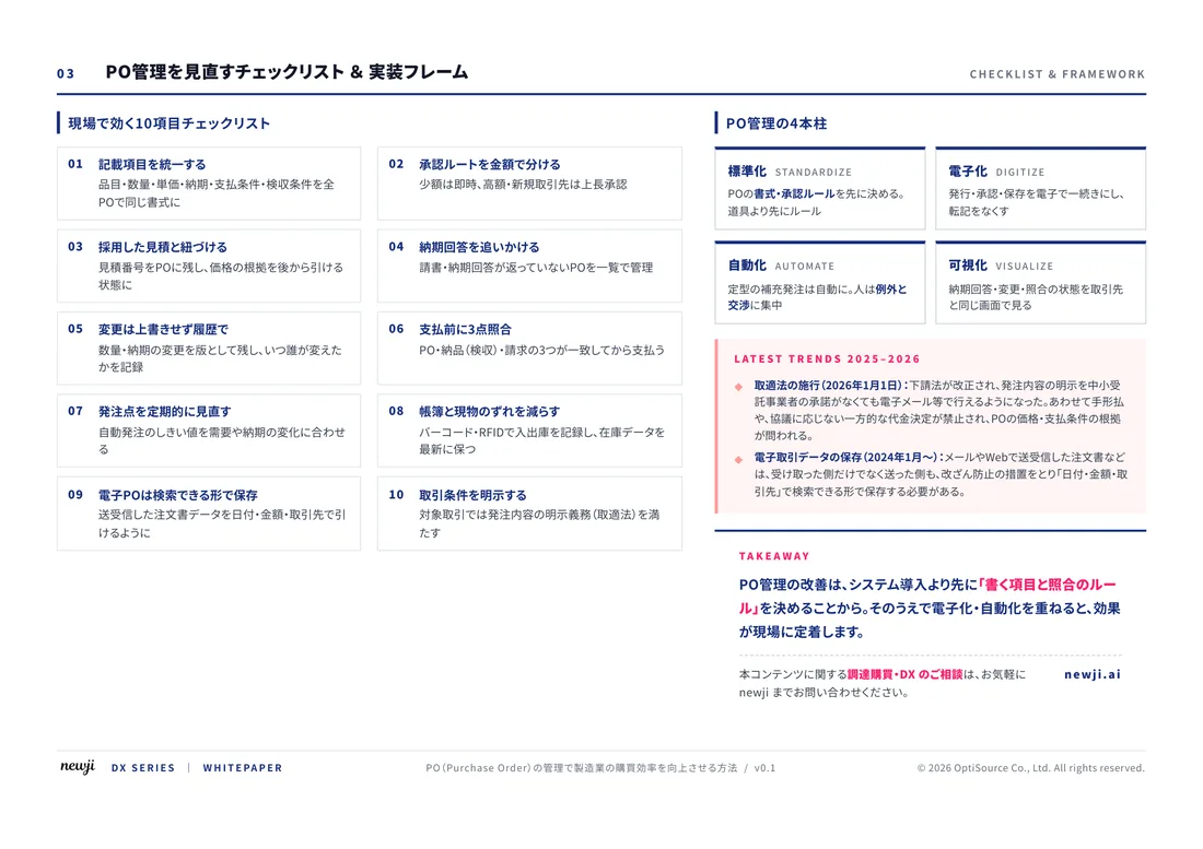
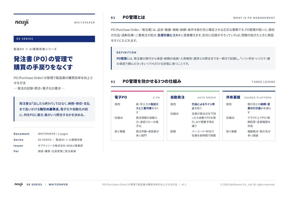
FREE DOCUMENT — サービス資料(PDF・無料)
製造業の見積・受発注クラウド
「Newji one」とは
Newji one は、製造業の調達・受発注に特化したクラウド/AIエージェント。見積依頼・発注書作成・進捗管理・承認をひとつの画面に集約し、AIが比較と異常検知を担当。最後の「GO」だけ人が押す仕組みです。
▶ 製造業の見積・受発注クラウド「Newji one」を、資料で見る(PDF・無料)
- 見積〜発注〜納期を一元管理。催促・転記のムダをゼロに
- AIが相見積もり比較と異常検知。あなたは判断だけに集中
- 取引先は「招待」で完全無料。自社コストだけで取引先ごとデジタル化
※ 取引先から招待された企業様は完全無料でご利用いただけます

 NEWJI総研
 OEM/ODM 生産委託
 AI/DX支援
 見積・発注クラウド Newji one
受発注が増えるほど、入力・確認・催促が重くなる。
受発注管理を“仕組み化“して、ミスと工数を削減しませんか。
見積・発注・納期まで一元管理できます。