

- お役立ち記事
- Basic principles of mechanical drawing and application to maximum geometric tolerance intersection

その単価は妥当か。
AI が根拠付きで分析。
相見積の比較も発注も進捗管理も、ひとつの画面に。

Basic principles of mechanical drawing and application to maximum geometric tolerance intersection

Mechanical drawing is an essential skill for engineers, architects, and designers, serving as a universal language that communicates complex ideas through precise diagrams. These drawings provide a visual representation of an object or system, detailing its dimensions, design, and specifications. Understanding the basic principles and applications of mechanical drawing is crucial for accurately interpreting and creating these technical diagrams.
目次
Understanding Mechanical Drawing
Mechanical drawing involves creating diagrams that represent mechanical objects or systems with exact and detailed measurements. It is a key component in fields like engineering and manufacturing, where precision is paramount.
Fundamentals of Mechanical Drawing
Mechanical drawings are composed of several standardized elements, including lines, symbols, and annotations that describe an object’s size, shape, and material. These elements must adhere to specific guidelines to ensure clarity and precision.
Types of Mechanical Drawings
There are several types of mechanical drawings, each serving distinct purposes. Some of the most common include:
– **Orthographic Projections:** These are two-dimensional representations of a three-dimensional object. Orthographic projections typically consist of multiple views (e.g., front, top, and side views) that provide comprehensive details of the object’s geometry.
– **Isometric Drawings:** Isometric drawings offer a three-dimensional perspective, presenting an object in a way that allows viewers to see the height, width, and depth in one view.
– **Sectional Views:** These drawings show an object as if it has been cut along a plane, revealing internal features that are typically hidden.
Importance of Precision and Consistency
In mechanical drawing, precision is crucial. Even the slightest deviation can lead to significant discrepancies in the final product. Consistency in following standards ensures that drawings are universally understandable, reducing the risk of errors.
Geometric Tolerance in Mechanical Drawings
Geometric tolerance defines the permissible limits of variation in a physical dimension. It is a vital aspect of mechanical drawing, ensuring that parts fit together correctly and function as intended.
The Concept of Geometric Tolerance
Geometric tolerances are specified using a symbolic language that communicates how much a feature on a part may deviate from its ideal geometry. These tolerances are essential in maintaining quality control and ensuring interoperability in manufacturing.
Application to Maximum Material Condition (MMC)
The term Maximum Material Condition refers to the state of a feature which contains the greatest amount of material within its size limits. For instance, in a hole, the MMC is the smallest permissible diameter, while in a shaft, it is the largest permissible diameter.
Understanding Intersection in Tolerance
Intersection in the context of geometric tolerance involves the overlap and interaction between different geometric features and their respective tolerances. Ensuring that these intersections fall within designated tolerances is crucial to achieving functional and reliable assemblies.
Practical Applications and Benefits
The integration of geometric tolerances in mechanical drawings offers substantial benefits, enhancing both the function and reliability of manufactured products.
Enhancing Manufacturing Processes
With precise geometric tolerancing, manufacturers can reduce waste, improve efficiency, and ensure components fit together perfectly. This precision helps streamline the production process and minimize errors.
Increasing Product Quality
Careful application of geometric tolerances leads to products that meet stringent quality standards. By controlling variations, manufacturers can produce products that consistently meet performance expectations.
Facilitating Communication Between Teams
Mechanical drawings with clear tolerance specifications improve communication between engineering, design, and manufacturing teams. This clarity helps all parties understand requirements, reducing the likelihood of misinterpretations.
Conclusion
Mechanical drawing is a vital skill that enables the creation and interpretation of detailed technical diagrams. Understanding the basic principles and applications of mechanical drawing, including geometric tolerances, is essential for ensuring accuracy, consistency, and quality in engineering and manufacturing. By adhering to these standards, professionals can effectively communicate complex ideas and manufacture products that meet precise specifications.
この記事の理解を深める
無料ホワイトペーパーをプレゼント
製造業の現場で使える実務資料(PDF)を無料でお届けします。"こんな資料が届きます" ↓ 下のボタンからどうぞ。
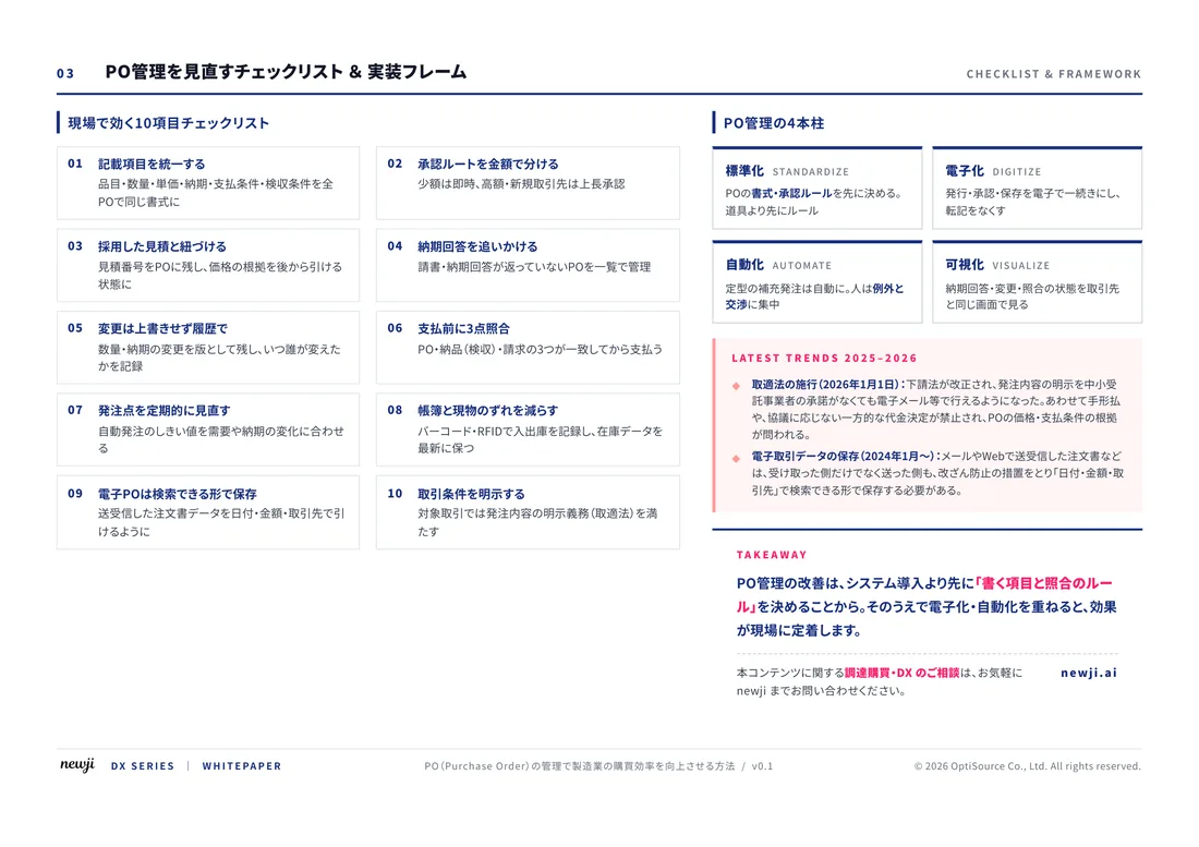
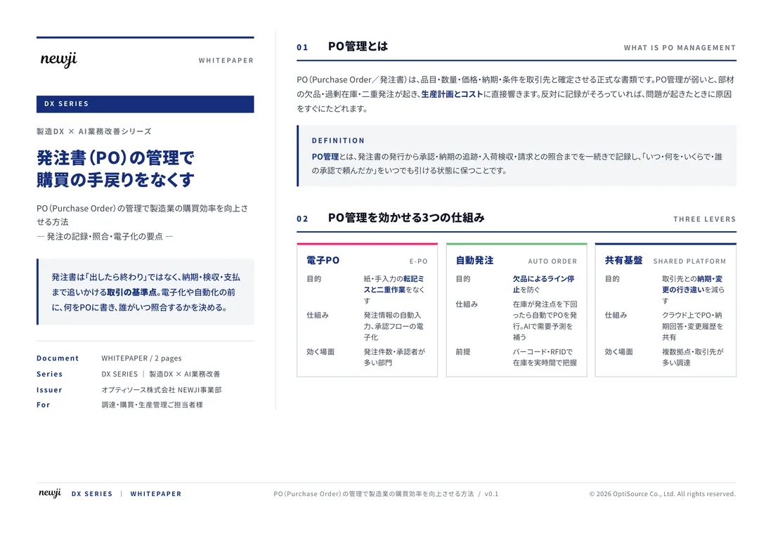
FREE DOCUMENT — サービス資料(PDF・無料)
製造業の見積・受発注クラウド
「Newji one」とは
Newji one は、製造業の調達・受発注に特化したクラウド/AIエージェント。見積依頼・発注書作成・進捗管理・承認をひとつの画面に集約し、AIが比較と異常検知を担当。最後の「GO」だけ人が押す仕組みです。
▶ 製造業の見積・受発注クラウド「Newji one」を、資料で見る(PDF・無料)
- 見積〜発注〜納期を一元管理。催促・転記のムダをゼロに
- AIが相見積もり比較と異常検知。あなたは判断だけに集中
- 取引先は「招待」で完全無料。自社コストだけで取引先ごとデジタル化
※ 取引先から招待された企業様は完全無料でご利用いただけます

 NEWJI総研
 OEM/ODM 生産委託
 AI/DX支援
 見積・発注クラウド Newji one
受発注が増えるほど、入力・確認・催促が重くなる。
受発注管理を“仕組み化“して、ミスと工数を削減しませんか。
見積・発注・納期まで一元管理できます。